[0009]In order to solve the above described and other shortcomings or drawbacks known in the conventional cross groove joints, the present invention provides a cross groove joint (preferably, but not necessarily, of higher ball type) with a compact and durable structure, in particular, with the strength of the cage web enhanced than that of the conventional cross groove joints as described above.
[0010]In order to provide an enhanced strength to the cage web of the cross groove joint, the present invention provides a cross groove joint including an outer joint member with a plurality of inwardly facing ball grooves and an inner joint member with a plurality of outwardly facing ball grooves, in which the shapes of the ball grooves of the outer and inner joint members are configured to increase the thickness and also the mechanical strength of the cage web as compared to the conventional cross groove joint as described above.
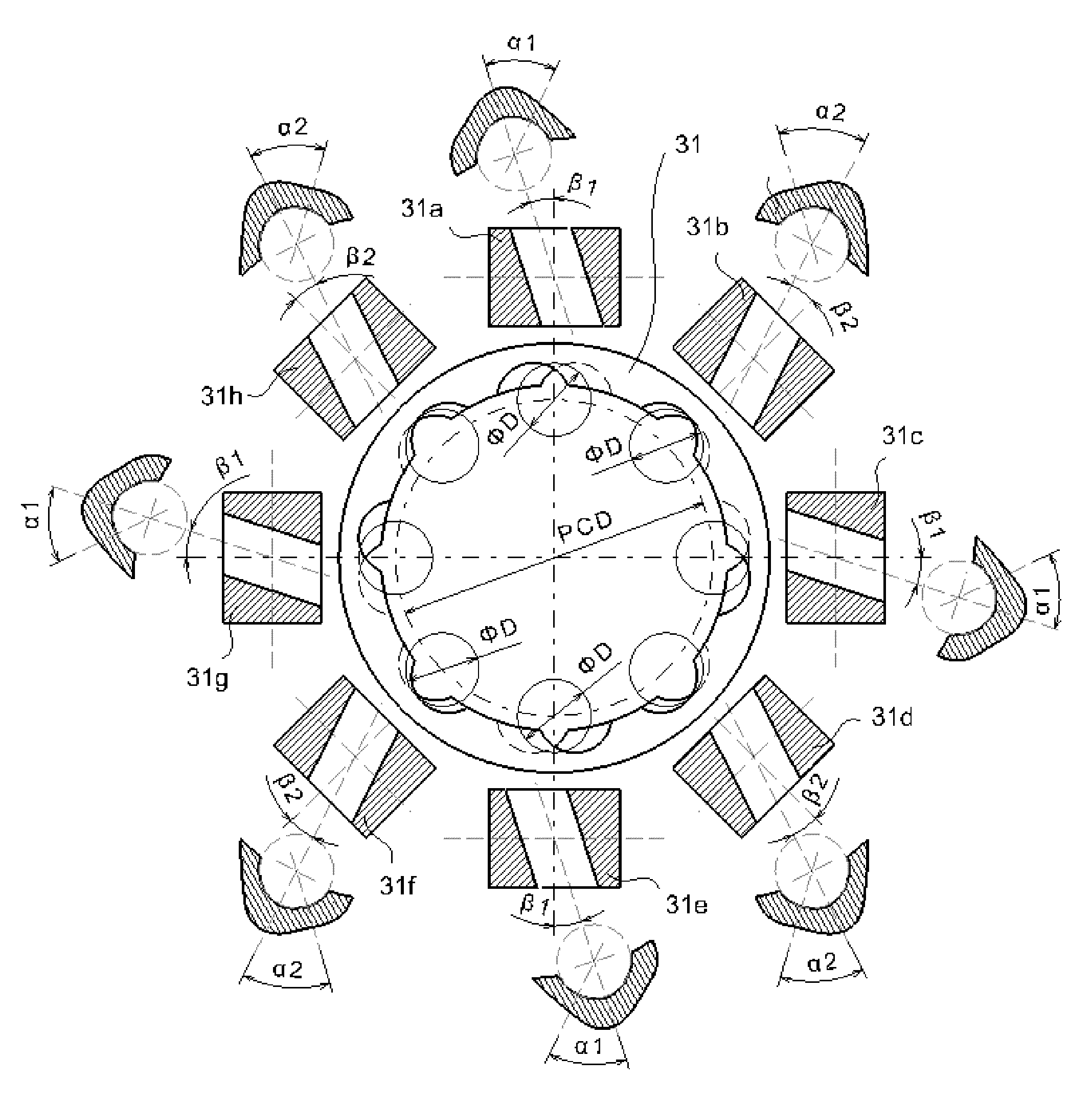
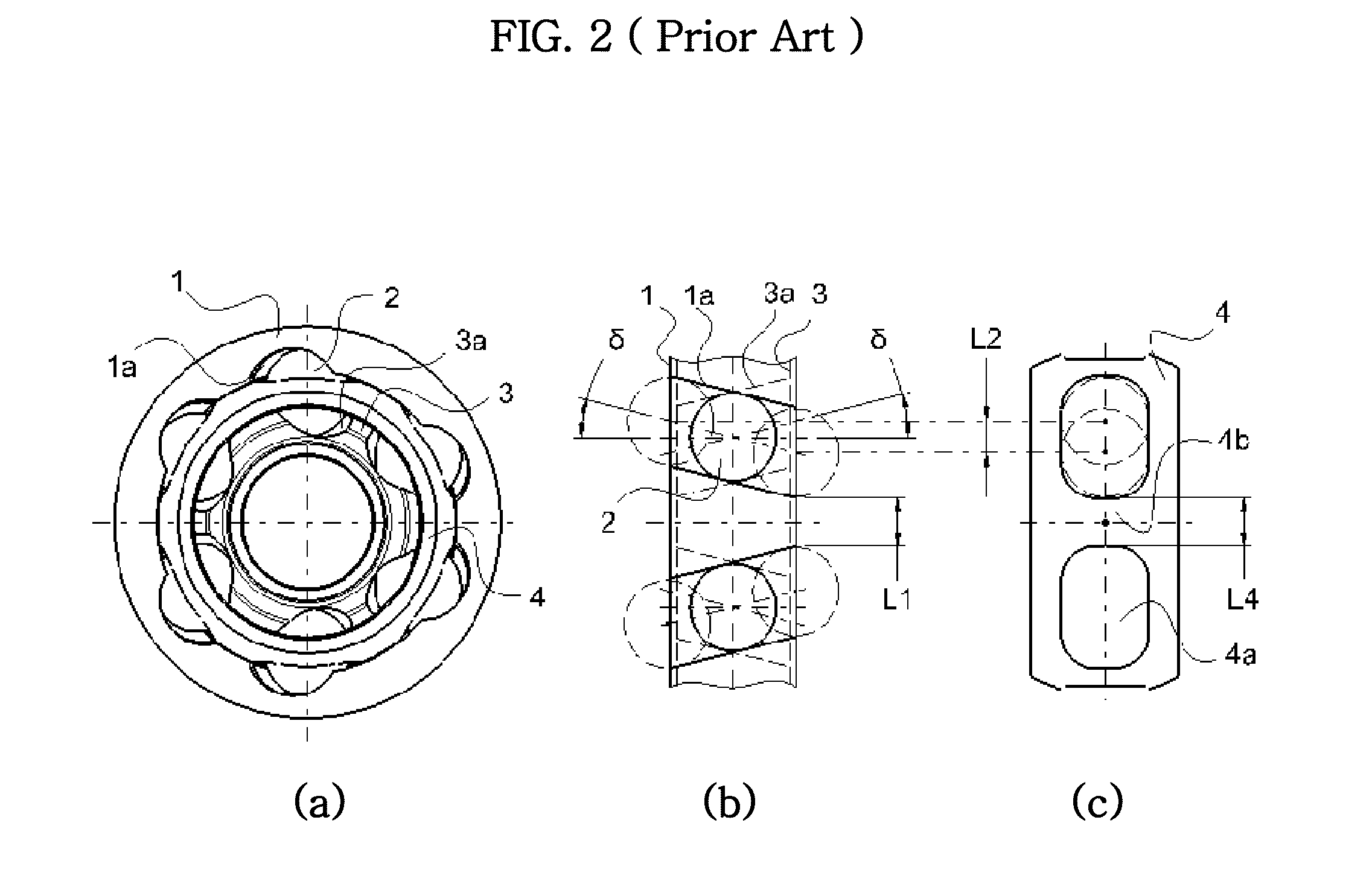
[0011]The mechanical strength and durability of the cage is influenced by skew angle δ (see FIG. 4, for example). As the skew angle δ of the ball grooves for the outer and inner joint members 11 and 33 increases, the ball movement L22 in circumferential direction increases and the size of cage window 44a should also be increase to accommodate the ball movement in the movement range. As a consequence, the thickness of cage web 44b between two adjacent windows 44a becomes smaller as the skew angle of the grooves for the inner and outer joint member increases. Therefore, considering all the factors described above, the applicant of the present application discovered several effective ways to reduce the ball movements and the size of cage windows in the cross groove joint (preferably, but not necessarily, of the type having eight or more balls) by decreasing or optimizing the skew angle and also optimizing the shapes of the ball grooves. U.S. patent application Ser. No. 12 / 563,029, filed Sep. 18, 2009 by the same applicants of the present application, suggests several examples of the constant velocity joints incorporating composite groove patterns (for example, such as a combination of liner and non-linear grooves, or of skewed grooves and non-linear grooves) to the ball grooves of the outer and inner joint members to provide an enhanced strength and durability comparing to the conventional cross groove type joint.
[0012]The present application provides a cross groove type constant velocity joint having outer and inner joint members with different groove configurations to the ball grooves of the outer and inner joint members to provide an enhanced strength and durability comparing to the conventional cross groove type joint. According to one aspect of the present invention, the ball grooves of the outer and inner joint members are configured to have two groups of skewed grooves composed of a first group with a skew angle as same as or similar to the skew angle (δ) of the conventional groove type joint (as shown in FIG. 4 for example) and a second group with a reduced skew angle which is less than the skew angle (δ) of the conventional groove type joint. As a result, the minimum thickness (L11) of the outer and inner joint members and the thickness of the cage web can be enlarged relative to the conventional groove type joint having the alternately arranged skewed grooves of the same skew angle (δ). Accordingly, the joint of the present invention can provide an enhanced strength and durability over the conventional cross groove type joint.
[0013]As described below in association with the eight ball type joint, for example, in order for the eight ball cross groove joint to secure the strength and durability of the cage to the level similar or equivalent to that of the six ball cross groove joint having the same pitch circle diameter (PCD), the skew angle is reduced and the minimum thickness (least effective thickness) of the outer and inner joint members (and thus, the thickness of the cage web as well) are maximized as compared to the conventional joint described above without any degradation of functions in the joint.
[0019]According to another aspect of the present invention, the shapes and configurations of the outer and inner joint members (including the ball grooves thereof) are further modified to provide an enhanced strength and durability, while also capable of reducing frictions and transmission errors in the joint causable by rotational backlash when using two groups of skewed grooves, one group with regular skew angles and the other with reduced skew angles. In order to resolve the potential risks of increasing the rotational backlash due to the reduced skew angle in the second group of grooves (which will be discussed below in details), the applicants discovered that the rotational backlash can be decreased as the contact angle between the ball and the ball groove for the inner and outer joint members increases and as the skew angle of the ball grooves increases. The applicants further discovered that the rotational backlash can also be decreased as the pitch circle diameter (PCD) increases. Based on these findings, the applicants further discovered several effective ways (as described below in details with reference to FIGS. 6-11) to reduce the rotational backlash in the ball grooves, while also maintaining a similar or equivalent strength and durability of the joint.

