Utility lamp system

a lamp system and lamp technology, applied in the field of utility lamps, can solve the problems of not being able to meet the needs of outdoor and indoor use in a convenient manner, and conventional lamp devices are not able to meet the needs of outdoor and indoor use for extended periods, and achieve the effect of compactness and durableness

Inactive Publication Date: 2006-09-26
JETLAND DAVID W
View PDF22 Cites 1 Cited by
  • Summary
  • Abstract
  • Description
  • Claims
  • Application Information

AI Technical Summary

Benefits of technology

[0017]Another object is to provide a utility lamp system that is durable and compact.

Problems solved by technology

While these lamp devices may be suitable for the particular purpose to which they address, they are not as suitable for use in outdoor and indoor locations in a convenient manner.
Conventional lamp devices are not suitable for usage within both outdoor and indoor locations for extended periods of time.

Method used


Image

  • Utility lamp system
  • Utility lamp system
  • Utility lamp system

Examples


Embodiment Construction

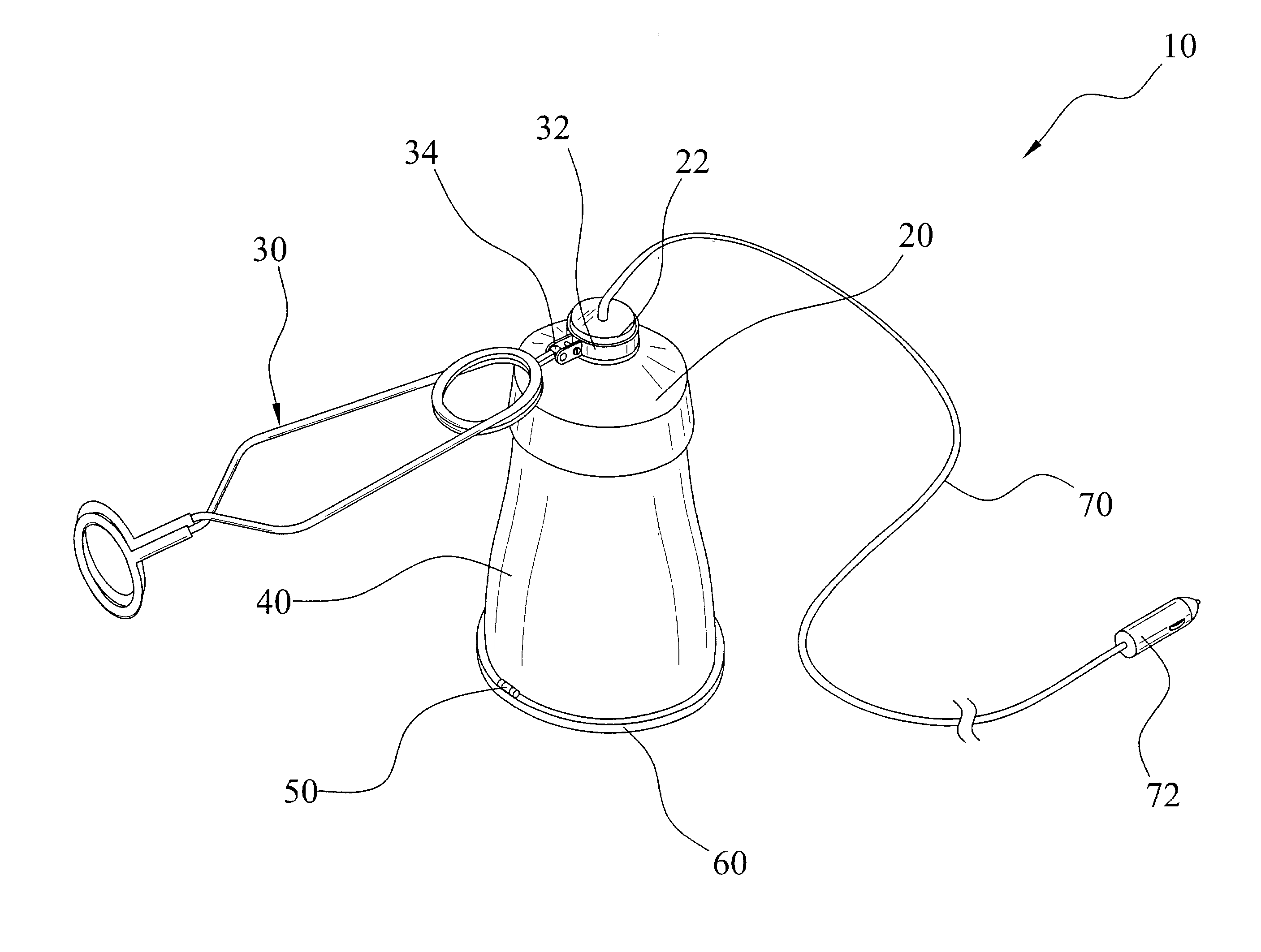
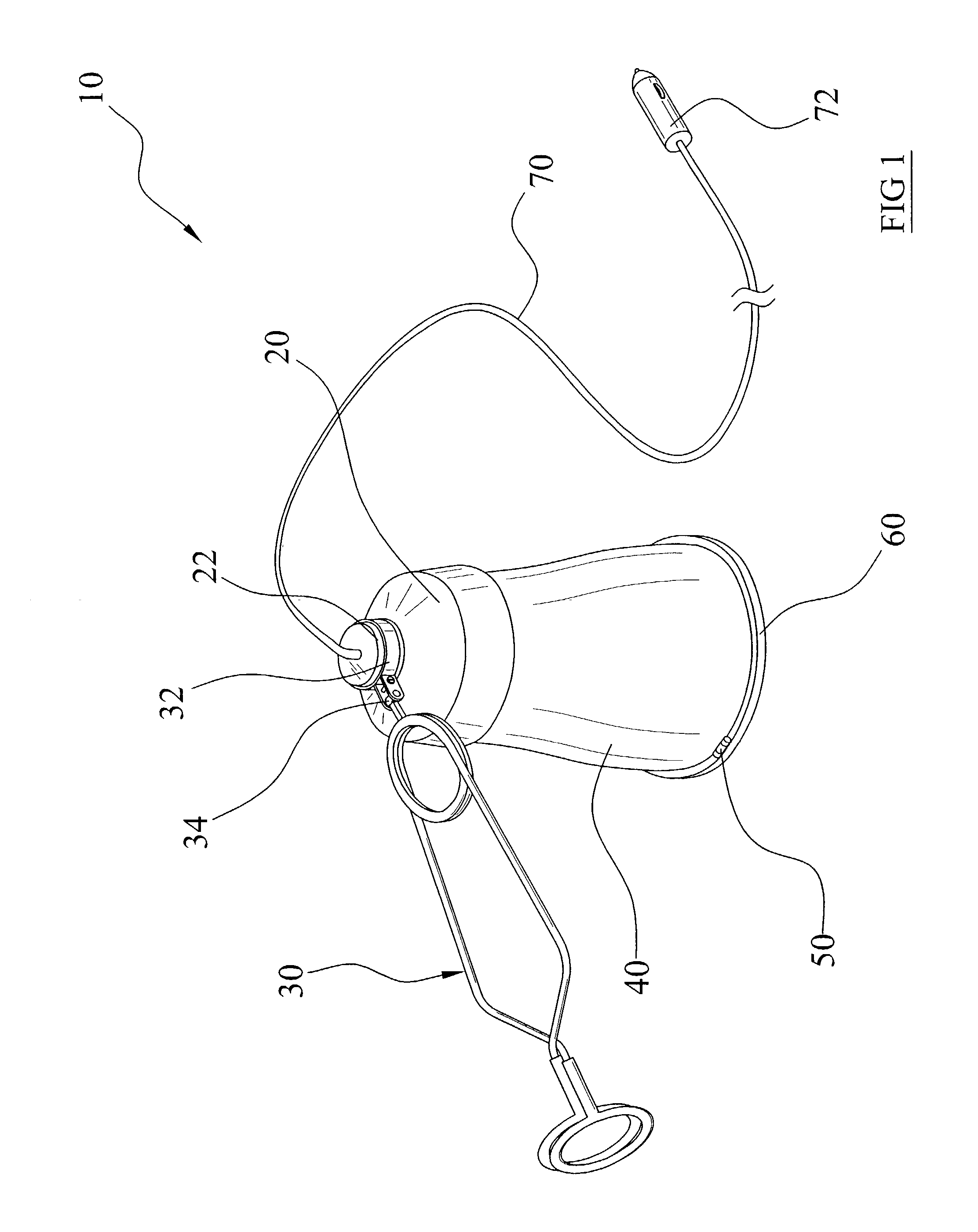
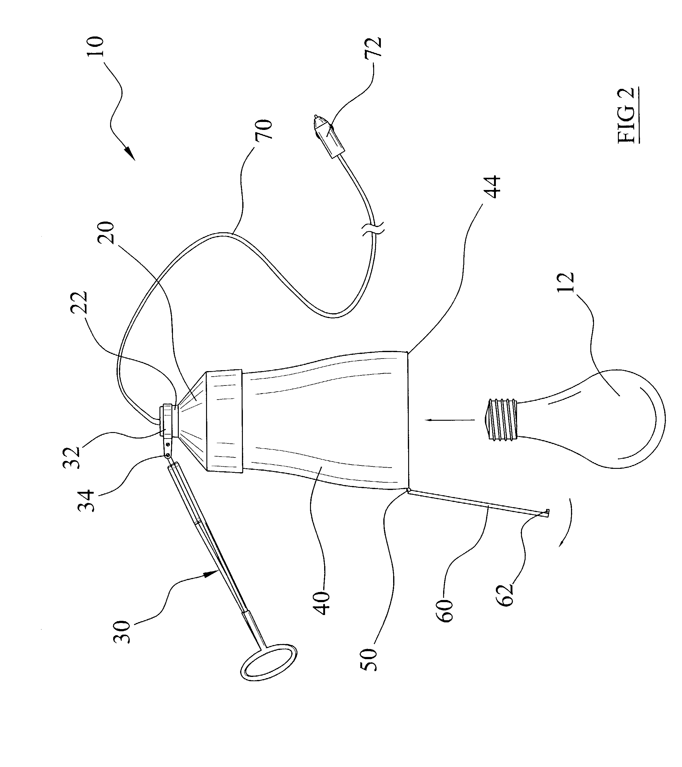
[0030]Turning now descriptively to the drawings, in which similar reference characters denote similar elements throughout the several view, FIGS. 1 through 6 illustrate a utility lamp system 10, which comprises a main housing 20 with an electrical receptacle within, a clamp structure 30 movably attached to the main housing 20, a bulb housing 40 extending from the main housing 20, and a cover 60 pivotally attached to a lower end 44 of the bulb housing 40.

[0031]As shown in FIG. 3 of the drawings, the main housing 20 has an upper neck 22 that is narrower than a main portion of the main housing 20. The main housing 20 has an electrical receptacle within for threadably and electrically receiving a conventional light bulb 12. A power cord 70 is electrically connected to the electrical receptacle for providing either DC or AC electrical power to the light bulb 12. An adapter unit 72 is preferably electrically connected to the distal end of the power cord 70 for electrically connecting to a...


PUM


Abstract

A utility lamp system for use in outdoor and indoor locations in a convenient manner. The device includes a main housing with an electrical receptacle within, a clamp structure movably attached to the main housing, a bulb housing extending from the main housing, and a cover pivotally attached to a lower end of the bulb housing.

Description

CROSS REFERENCE TO RELATED APPLICATIONS[0001]Not applicable to this application.STATEMENT REGARDING FEDERALLY SPONSORED RESEARCH OR DEVELOPMENT[0002]Not applicable to this application.BACKGROUND OF THE INVENTION[0003]1. Field of the Invention[0004]The present invention relates generally to utility lamps and more specifically it relates to a utility lamp system for use in outdoor and indoor locations in a convenient manner.[0005]2. Description of the Related Art[0006]Examples of patented devices which may be related to the present invention include U.S. Pat. No. 6,062,703 to Tsao; U.S. Pat. No. 360,952 to Lee; U.S. Pat. No. 6,315,431 to Greedy; U.S. Pat. No. 5,209,562 to Glassford; U.S. Pat. No. 5,769,535 to Rominger et al.; U.S. Pat. No. 367,540 to Lee; U.S. Pat. No. 5,961,207 to Petkovic; U.S. Pat. No. 5,769,526 to Shaffer; U.S. Pat. No. 5,548,496 to Hart et al.; U.S. Pat. No. 5,510,970 to Hollenbach et al.; U.S. Pat. No. 5,645,341 to Liao; U.S. Pat. No. 5,602,948 to Currie; U.S. P...

Claims


Application Information

Patent Timeline
Patent Type & Authority Patents(United States)
IPC IPC(8): F21V21/08F21V14/02F21L14/02F21V21/088F21V21/30F21V23/06
CPCF21L14/02F21V21/0885F21V23/06F21V21/30
Inventor JETLAND, DAVID W.
Owner JETLAND DAVID W
Why Eureka
Try Eureka