
Method for making carbon nanotube wire structure

a carbon nanotube and wire structure technology, applied in the field of carbon nanotube wire structure making methods, can solve the problems of difficult production of large silicon substrates, limited application of carbon nanotubes by particle or powder-shaped carbon nanotubes, and limited diameter of yarn made by the method

Active Publication Date: 2013-05-21
TSINGHUA UNIV +1
View PDF10 Cites 17 Cited by
  • Summary
  • Abstract
  • Description
  • Claims
  • Application Information

AI Technical Summary

Benefits of technology

The patent text describes a method for making yarn by twisting carbon nanotubes with a small diameter, which limits its use in applications that require stronger yarn. The technical effect of the patent is to provide a method for making larger yarn with better strength and toughness.

Problems solved by technology

The particle or powder-shaped carbon nanotubes limit the applications of the carbon nanotubes.
However, a diameter of the yarn made by the method is restricted by a scale of the carbon nanotube array.
A large silicon substrate is difficult to produce using the present silicon technology.
Therefore, it is difficult to acquire a large area of the carbon nanotube array.
Thus, the yarn twisted by the pre-primary assembly has a small diameter and the mechanical strength and toughness of the yarn is inferior, thereby limiting its application.

Method used


Image

  • Method for making carbon nanotube wire structure
  • Method for making carbon nanotube wire structure
  • Method for making carbon nanotube wire structure

Examples


Embodiment Construction

[0016]The disclosure is illustrated by way of example and not by way of limitation in the figures of the accompanying drawings in which like references indicate similar elements. It should be noted that references to “an” or “one” embodiment in this disclosure are not necessarily to the same embodiment, and such references mean at least one.

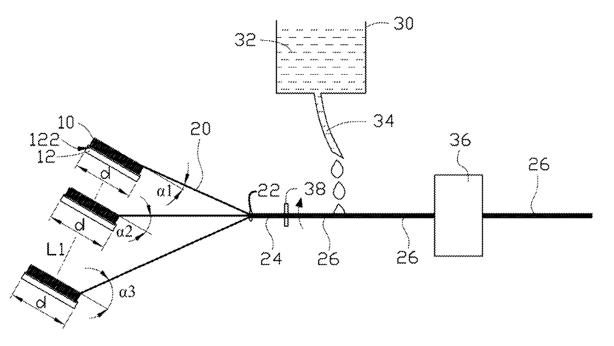
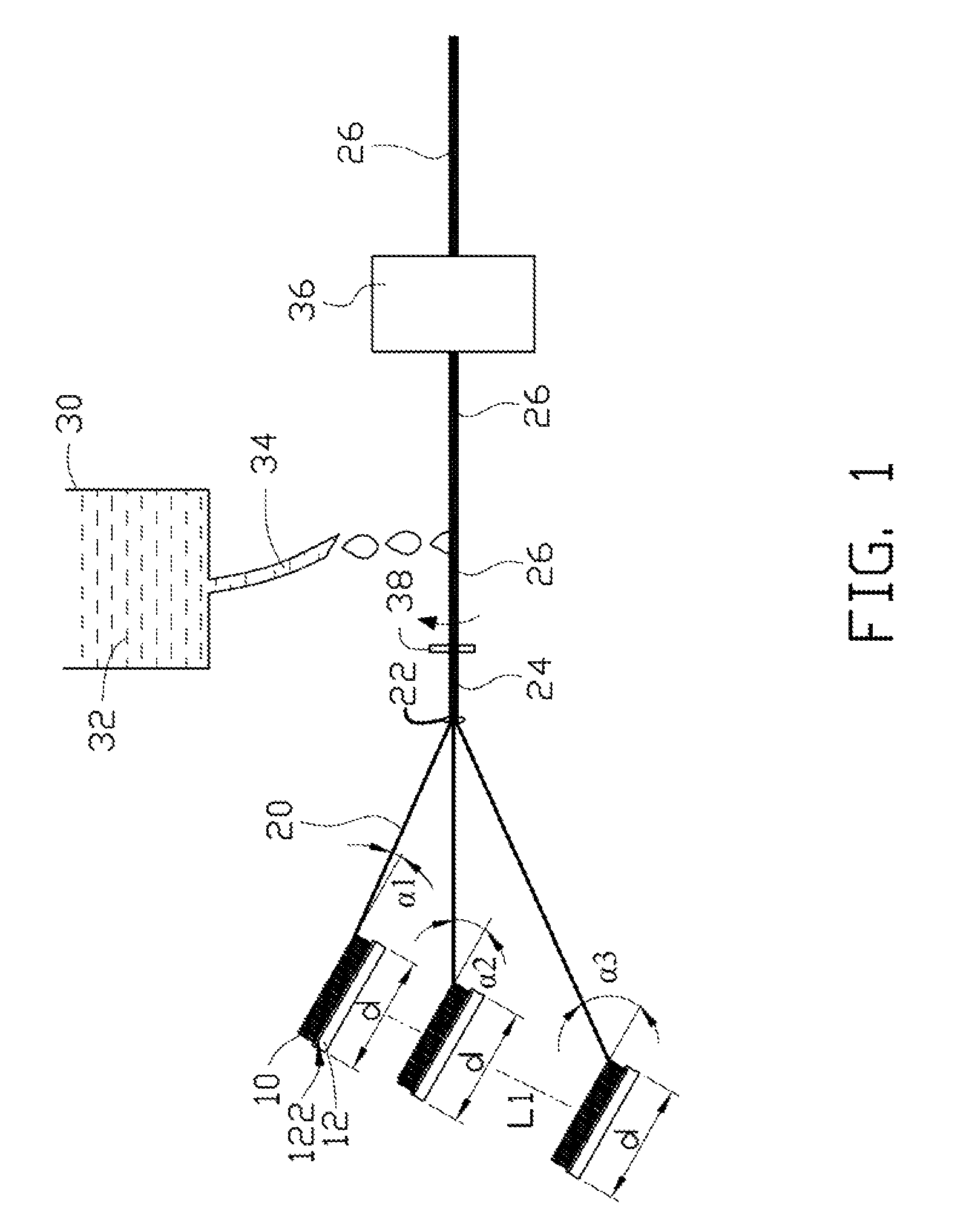
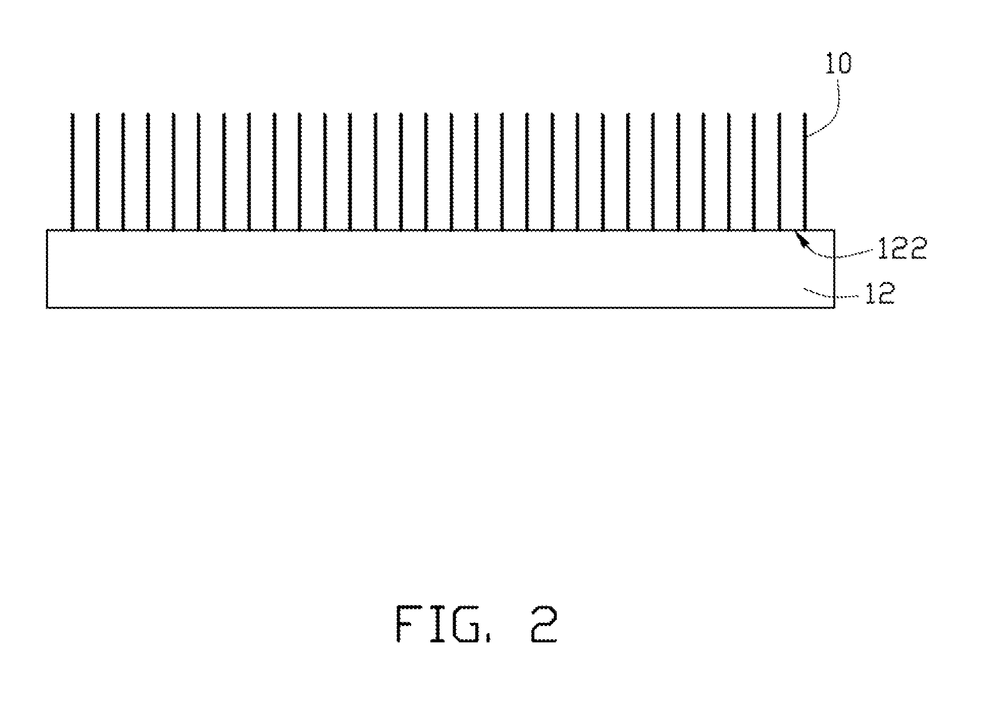
[0017]Referring to FIG. 1 and FIG. 2, one embodiment of a method for making a carbon nanotube wire structure is provided. The method includes:

[0018](S1) providing a plurality of carbon nanotube arrays 10, each of the carbon nanotube arrays 10 is formed on a top surface 122 of a substrate 12, and the top surfaces 122 of the plurality of substrates 12 are in different planes;

[0019](S2) forming a plurality of carbon nanotube films, each carbon nanotube film 20 formed by drawing a number of carbon nanotubes from each of the plurality of carbon nanotube arrays 10, wherein an angle between the drawing direction and the surface 122 of each substrate 12 ...


PUM

PropertyMeasurementUnit
angleaaaaaaaaaa
angleaaaaaaaaaa
angle α3aaaaaaaaaa

Abstract

The present disclosure provides a method for making a carbon nanotube wire structure. A plurality of carbon nanotube arrays is provided. One carbon nanotube film is formed by drawing a number of carbon nanotubes from each of the plurality of carbon nanotube arrays, whereby a plurality of carbon nanotube films is formed. The carbon nanotube films converge at one spot. The carbon nanotube wire structure is formed by treating the carbon nanotube films by at least one of a mechanical method and an organic solvent method.

Description

RELATED APPLICATIONS[0001]This application claims all benefits accruing under 35 U.S.C. §119 from China Patent Application No. 200910189915.0, filed on Aug. 28, 2009 in the China Intellectual Property Office. The application is also related to copending application entitled, “METHOD FOR MAKING CARBON NANOTUBE WIRE STRUCTURE”, filed Nov. 19, 2009, Ser. No. 12 / 621,512.BACKGROUND[0002]1. Technical Field[0003]The present disclosure relates to methods for making carbon nanotube wire structure.[0004]2. Discussion of Related Art[0005]Carbon nanotubes can be composed of a plurality of coaxial cylinders of graphite sheets. Carbon nanotubes have received a great deal of interest since the early 1990s. Carbon nanotubes have interesting and potentially useful electrical and mechanical properties. Due to these and other properties, carbon nanotubes have become a significant focus of research and development for use in electron emitting devices, sensors, transistors, and other devices.[0006]Gener...

Claims


Application Information

Patent Timeline
Patent Type & Authority Patents(United States)
IPC IPC(8): D01F9/12
CPCB82Y30/00B82Y40/00C01B31/0253D06M13/144D06M2101/40D10B2101/122C01B32/168
Inventor FENG, CHENJIANG, KAI-LIFAN, SHOU-SHAN
Owner TSINGHUA UNIV
Learn More