Vacuum cartridge for an electrical protection apparatus such as a switch or a circuit breaker

a technology for electrical protection equipment and vacuum cartridges, which is applied in the direction of electrical apparatus, air-break switches, high-tension/heavy-dress switches, etc., can solve the problems of unbalanced distribution of potential outside, explosion and fire risk, and extremely dangerous flashovers between contacts and shields, etc., to achieve simple design, improve electrical behaviour, and reduce the size of cartridges

Active Publication Date: 2013-05-21
SCHNEIDER ELECTRIC IND SAS
View PDF5 Cites 12 Cited by
  • Summary
  • Abstract
  • Description
  • Claims
  • Application Information

AI Technical Summary

Benefits of technology

[0010]The present invention solves these problems and proposes a vacuum cartridge of simple design whereby the size of cartridges and therefore the cost thereof can be substantially reduced, and their electrical behaviour be improved.

Problems solved by technology

These flashovers between the contacts and shield are extremely dangerous, for when such a flashover occurs, the shield temporarily goes to the potential of the contact (doubling of the potential on the shield) and the distribution of the potential outside is unbalanced with a distribution of 100% of the potential on 50% of the length of the external insulation.
This situation can degenerate into an external flashover generating a risk of explosion and fire.
The drawback of this type of cartridge lies in the fact that it presents a large diameter.
In addition, the higher the application voltage, the larger the distance between the contacts and the length of the ceramics has to be.
This increase of the diameter of the shield is however detrimental in terms of cost of the switchgear units and of electrical behaviour.
Indeed, the diameter of the ceramics is proportional to the diameter of the shield, which gives rise to extra cost.
Moreover, if an external insulation is provided around the cartridge, the diameter of the outside enclosure also increases with the diameter of the cartridge, which also generates additional cost.

Method used


Image

  • Vacuum cartridge for an electrical protection apparatus such as a switch or a circuit breaker
  • Vacuum cartridge for an electrical protection apparatus such as a switch or a circuit breaker
  • Vacuum cartridge for an electrical protection apparatus such as a switch or a circuit breaker

Examples


Embodiment Construction

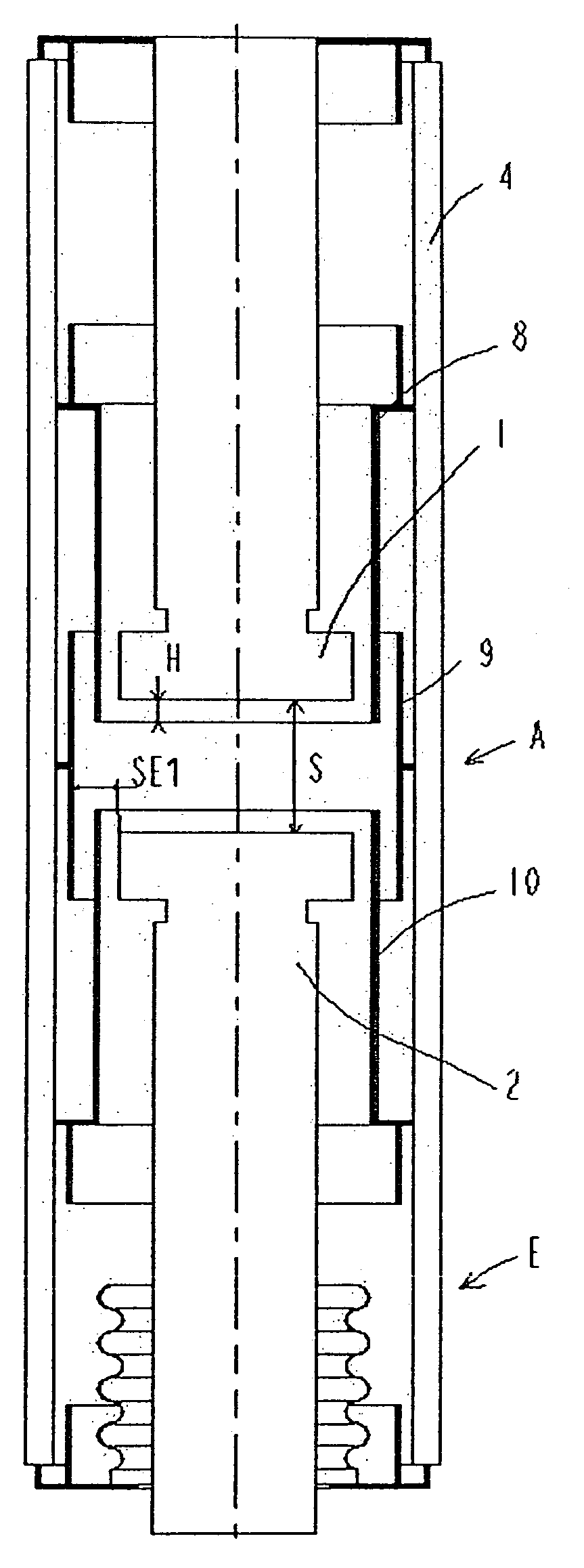
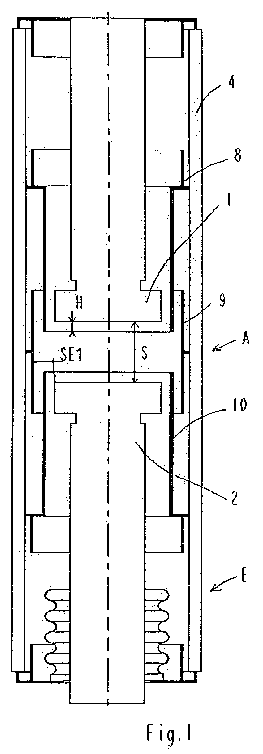
[0032]In FIGS. 1, 3, 4 and 5, a vacuum cartridge A can be seen designed in particular to be integrated in a medium-voltage electric circuit breaker to perform breaking of an electric circuit in the event of a fault or when a deliberate opening action of the electric circuit is performed.

[0033]This vacuum cartridge A comprises in a manner known as such a cylindrical enclosure E closed off by two end-plates inside which two arcing contacts are housed, respectively a stationary arcing contact 1 and a movable arcing contact 2. This movable contact 2 is mechanically connected by means of an actuating rod to an operating device (not shown), said rod being connected to said device via one of its ends and being securedly fixed to the movable arcing contact via its opposite end. This operating device is able to move the afore-mentioned rod and the movable contact in translation inside the enclosure between two positions, respectively a closed position of the contacts corresponding to normal ...


PUM


Abstract

A cartridge having at least three shields including a mid-potential shield between two contacts and at least one partial shield between a mid-potential shield and one of the contacts, the distance between the mid-potential shield and the contacts being such that the electric field present at the edge of the contact extends from the contact to the partial shield surrounding it, or vice-versa from the partial shield to the contact, depending on the polarity of the voltage.

Description

[0001]The present application is based on International Application PCT / FR2006 / 001274, filed Jun. 6, 2006, which claims priority to French Patent Application No. 0506550, filed Jun. 28, 2005, the entire contents of which are hereby incorporated by reference.BACKGROUND OF THE INVENTION[0002]The present invention relates to a vacuum cartridge for an electrical protection apparatus such as a disconnecting switch, a switch or a circuit breaker, said cartridge comprising an enclosure of substantially cylindrical shape closed off by two end-plates, two contacts extending axially inside the enclosure, at least one of these contacts, the movable contact, being connected to an operating mechanism and mounted sliding between a closed position of the contacts enabling flow of the current and a position in which the contacts are separated and withstand the voltage between them, and at least one conducting shield arranged around at least one of the contacts.[0003]In the most commonly used shield...

Claims


Application Information

Patent Timeline
Patent Type & Authority Patents(United States)
IPC IPC(8): H01H33/66
CPCH01H33/66261H01H2033/66292H01H2033/66284
Inventor SCHELLEKENS, HANSOLIVE, SERGECARDOLETTI, OLIVIERYVARS, BERNARD
Owner SCHNEIDER ELECTRIC IND SAS
Why Eureka
Try Eureka