Lighting arrangement using LEDs

a technology of led lights and led lights, applied in the field of led lights, can solve the problems of limited process, affecting the design and appearance of finished signs, and brittleness of neon tubes, so as to achieve positive effects on user experien

Active Publication Date: 2013-05-28
C M GLO
View PDF109 Cites 10 Cited by
  • Summary
  • Abstract
  • Description
  • Claims
  • Application Information

AI Technical Summary

Benefits of technology

[0005]The present inventors have recognized that a significant feature of an illuminated sign is the structure and appearance of the light-emitting waveguide. Providing a waveguide that is practical, structurally and in terms of material cost, and novel or attractive, can positively affect the user's experience with the illuminated sign.
[0006]Specifically, the invention contemplates a simulated neon light including at least one elongated translucent diffuser or waveguide having an inner surface, an outer surface, and a hollow interior. The outer surface of the diffuser has a flat top portion extending substantially over the length of the elongated translucent diffuser. The light includes a housing that is configured for attachment to the translucent diffuser, and a series of light emitting diodes contained within the housing and aligned with a long axis of the elongated translucent diffuser. With this construction, the light emitting diodes when energized emit light that strikes the inner surface of the elongated translucent diffuser, such that a portion of the light is diffused and emitted by the flat portion of the outer surface. An electrical power source energizes the light emitting diodes. The simulated neon light thus has a novel look for attracting the user and enhancing their visual experience.

Problems solved by technology

Neon tubes tend to be very brittle and susceptible to accidental breakage.
The process is thus limited by the constraints of illuminating the tube with neon gas within, and the constraints imposed by the available traditional neon glass tubing which limits the design and appearance of the finished sign and requires a substantially complex fabrication process.
Further, neon tubing is relatively expensive and thus replacement of the tubes is undesirable and cost prohibitive.

Method used


Image

  • Lighting arrangement using LEDs
  • Lighting arrangement using LEDs
  • Lighting arrangement using LEDs

Examples


embodiment 90

[0055]Turning to FIG. 8a, in another embodiment 90, the housing 26 has top edges 64 which receive the diffuser 25 to attach the housing 26 to the waveguide bottom wall 38.

[0056]Referring now to FIG. 8b, in yet another embodiment 100, the housing 26 has top edges 64 which receive the open diffuser 24 to attach the housing 26 to the waveguide bottom edges.

embodiment 110

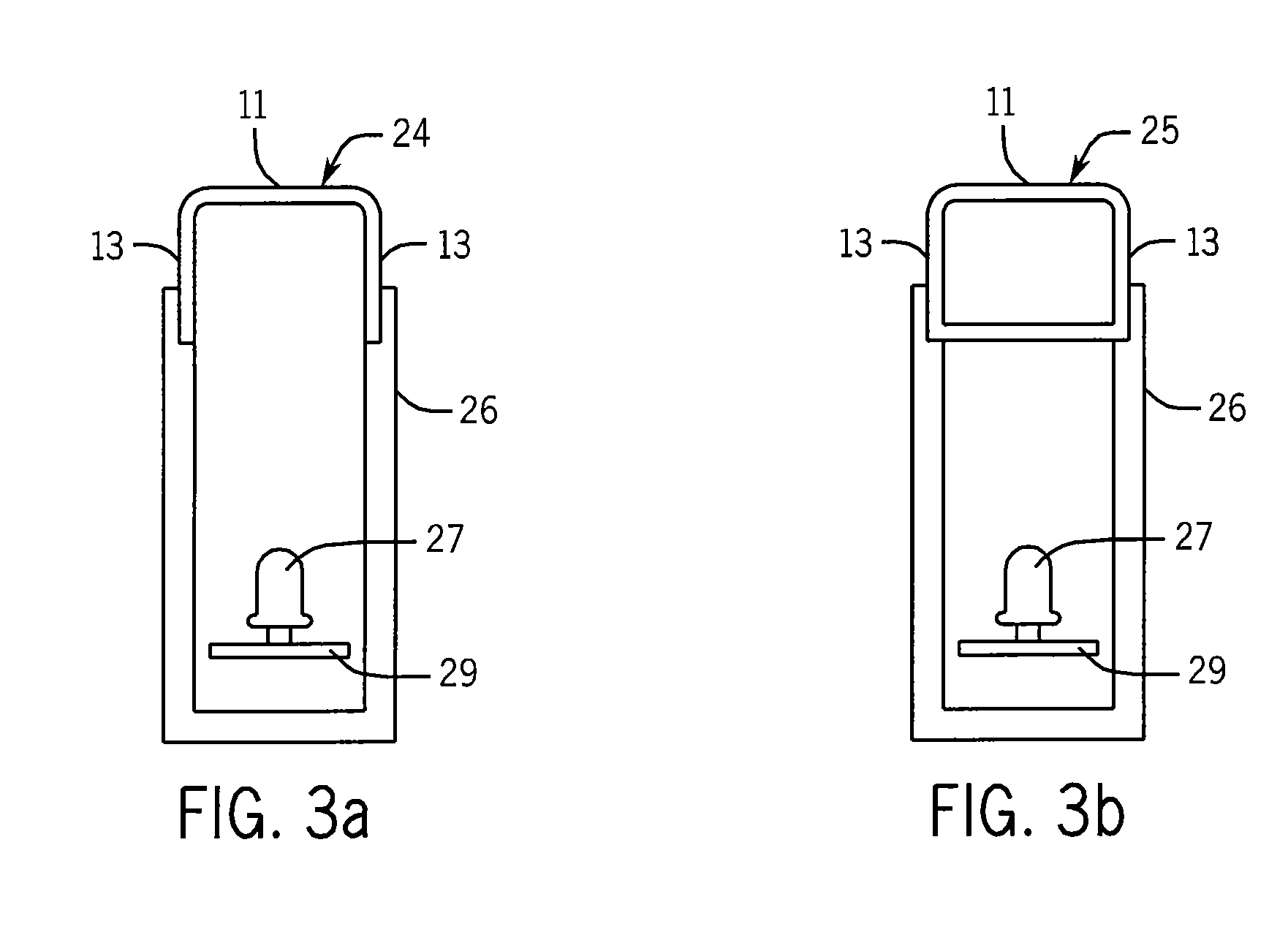
[0057]Turning to FIG. 9a, in another embodiment 110, the housing 26′ is substantially solid and has arms 160 and a surface 126 configured to receive the closed diffuser 25. The closed diffuser 25 contains the LEDs 27 and supporting structure 29.

embodiment 120

[0058]Referring now to FIG. 9b, in another embodiment 120, the housing 26′ is substantially solid and has arms 160 and a surface 126 configured to receive the open diffuser 24. The open diffuser 24 contains the LEDs 27 and supporting structure 29.

[0059]Referring to FIGS. 10a-10c, the embodiments 130, 140, 150 show differing widths of the housing 26 relative to the diffuser. Referring to FIG. 10a, an embodiment of the present invention 130 may have a housing 26″ that is substantially solid that receives the closed diffuser 25 on a top surface 326 that is narrower than the bottom 38 to which the diffuser 25 is attached, with the diffuser 25 having the LEDs 27 and circuit board assembly 29 mounted within.


PUM


Abstract

A lighting arrangement using LEDs that has an elongated translucent diffuser having a flat upper surface along the length of the diffuser. The transverse cross-section of the elongate translucent diffuser may have various shapes, all having substantially flat tops, including but not limited to quadrangular, rectangular, trapezoidal, and non-isosceles variations of these shapes. The elongated translucent diffuser is mounted on an elongated housing of substantially the same length to support the diffuser. The elongated housing may be solid or hollow and may contain the LEDs and circuit board, or the LEDs and circuit board may be contained within the elongated translucent diffuser. The LEDs are configured to transmit light through the diffuser so that the emitted light simulates light from a traditional neon tube.

Description

CROSS-REFERENCE TO RELATED APPLICATIONS[0001]This application claims priority to U.S. Provisional Patent Application Ser. No. 61 / 243,800 filed on Sep. 18, 2009, the entirety of which is hereby incorporated by reference.BACKGROUND OF THE INVENTION[0002]The present invention relates generally to a sign, and more particularly to an illuminated sign incorporating an elongate diffuser or waveguide which provides a novel and attractive surface for emitting substantially uniform light.[0003]Signs for storefronts and the like are well known throughout the art. For instance, signs for indicating whether a particular business is open, i.e., open signs, and the like are well known. Such signs have traditionally utilized neon for illumination of the sign. In such signs, a number of tubes are arranged to spell out the word or words desired such as, e.g., “OPEN”. Such tubes, traditionally round hollow glass, are filled with neon, argon, xenon, or other gases, and an electrical charge is applied t...

Claims


Application Information

Patent Timeline
Patent Type & Authority Patents(United States)
IPC IPC(8): F21V1/00
CPCF21V3/04G09F13/0404G09F13/0409G09F13/0413G09F13/08G09F13/22F21W2111/00F21Y2101/02F21Y2103/003G09F2013/222F21Y2103/10F21Y2115/10
Inventor MARTIN, JOHN D.LUTZ, CHAMY CHIACHENSMALL, LISA M.
Owner C M GLO
Why Eureka
Try Eureka