Car light unit and car light

A technology for car lamps and lens parts, applied in lighting and heating equipment, semiconductor devices of light-emitting elements, lighting devices, etc., can solve the problems of low light utilization rate and reduced light utilization rate, and achieve high-quality feeling and novel appearance Effect

Active Publication Date: 2013-03-06
STANLEY ELECTRIC CO LTD
View PDF6 Cites 10 Cited by
  • Summary
  • Abstract
  • Description
  • Claims
  • Application Information

AI Technical Summary

Problems solved by technology

[0005] However, in the vehicle light 700 of the above-mentioned configuration, although the LED light source can be converted into a laterally long line light-emitting portion, the vehicle light has a disadvantage in that because the configuration mainly uses light emitted from the LED light source The light in the direction of the small angle of the optical axis, so the light utilization rate is low
[0006] Moreover, there is also a disadvantage in that since the above-mentioned reflective mirrors 721 to 724 that have been mirror-treated by sputtering or the like are configured to reflect light twice, and light loss (about 30%) may occur due to the double reflection, the light utilization efficiency is low. further reduce

Method used


Image

  • Car light unit and car light
  • Car light unit and car light
  • Car light unit and car light

Examples


Embodiment Construction

[0061] A vehicle light of the presently disclosed subject matter will now be described according to exemplary embodiments with reference to the accompanying drawings.

[0062] It should be understood that in some cases the following description will be given using the directions of "upper", "lower (low)", "front", "rear (back)", "left" and "right", and that these directions will be based on Orientation when the light is mounted on the body of the vehicle. This means giving directions from the driver's point of view.

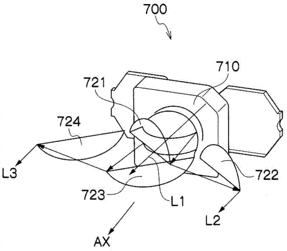
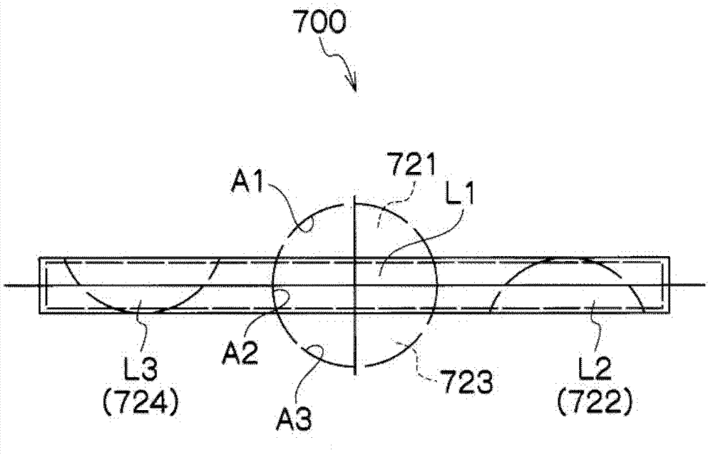
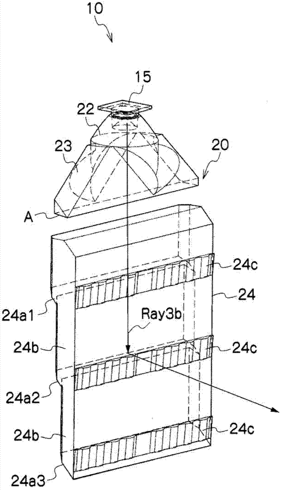
[0063] The vehicle light unit 10 according to this exemplary embodiment of the presently disclosed subject matter can be applied, for example, to signal lights for vehicles (eg, tail lights, brake lights, turn signal lights, daytime running lights, position lights, etc.). Such as Figure 2 to Figure 4 As shown, the vehicle lamp unit 10 may include components such as an LED light source 15 and a lens body 20 .

[0064] The LED light source 15 may be, for example,...


PUM


Abstract

The invention relates to a car light unit and a car light. The car light unit is capable of converting an LED (Light Emitting Diode) light source to a linear light emitting state and combining into the car light. The light car unit can comprise first to fourth lens parts which are arranged in front of the LED light source. Through providing first to fourth total reflection planes utilizing internal reflection to the third lens part, the first to third lens parts are capable of converting a point light source or the LED light source to a linear light emitting part and improving the light utilization rate at the same time. The light penetrating trough the linear light emitting part can come onto the fourth lens part. The fourth lens part can comprise a plate-shaped light guide part which has a plurality of total reflection planes on one surface and has corresponding lens incision parts on the opposite surface.

Description

technical field [0001] The presently disclosed subject matter relates to a vehicle light unit, and more particularly, to a vehicle light unit capable of converting an LED light source into a line lighting state, and a vehicle light utilizing the vehicle light unit. Background technique [0002] Conventional vehicle lights include optical systems configured such that LED light sources are converted into laterally long line light emitting portions (see, eg, Japanese Patent Application Laid-Open No. 2007-287490, or corresponding US Patent No. 7,441,928). [0003] Such as Figure 1A and Figure 1B As shown, the vehicle lamp 700 described in Japanese Patent Application Laid-Open No. 2007-287490 may be provided with: an LED light source 710; The first reflector 721 arranged in the upper region A1 in the region generated by the lower region A3); the second reflector 722 arranged on the outside of the first reflector 721; the third reflector 722 arranged in the lower region A3 mir...

Claims


Application Information

Patent Timeline
Patent Type & Authority Applications(China)
IPC IPC(8): F21S8/10F21V5/04F21Y101/02F21Y115/10
Inventor 二见隆
Owner STANLEY ELECTRIC CO LTD
Why Eureka
Try Eureka