Sports grip sensor

a technology of grip sensor and grip, which is applied in the field of sports grip sensor, can solve the problems of inability to address hand grip forces directly affecting swings, inability to inability to accurately measure hand grip forces, etc., and achieves the effect of improving grip tightness and being convenient to us

Inactive Publication Date: 2013-05-28
KAUFMAN ALEXANDER
View PDF13 Cites 19 Cited by
  • Summary
  • Abstract
  • Description
  • Claims
  • Application Information

AI Technical Summary

Benefits of technology

The invention is a training device that helps improve the grip of a racket by using a pressure sensor mounted on the handle of the racket. The device is adjustable so that the player can fine-tune the racket to alert at the correct grip tightness. The device is compact and easy to use.

Problems solved by technology

The patent text discusses the problem of measuring forces exerted on training devices by the human hand, which is a complex mechanism. Existing devices are expensive, not portable, and difficult to interpret. The technical problem is to provide a practical and cost-effective solution for measuring hand forces during a swing in a meaningful and accurate way.

Method used


Image

  • Sports grip sensor
  • Sports grip sensor
  • Sports grip sensor

Examples


Embodiment Construction

[0026]The best mode for carrying out the invention is presented in terms of a preferred embodiment for a sports grip sensor that is disclosed in two design configurations. The first design is shown in FIGS. 1-5 and the second design is shown in FIGS. 1 and 6. Both design configurations utilize a sports grip sensor that activates an alarm when a user of an athletic device such as a tennis racquet or a gulf club is applying an excessive force to the sports grip.

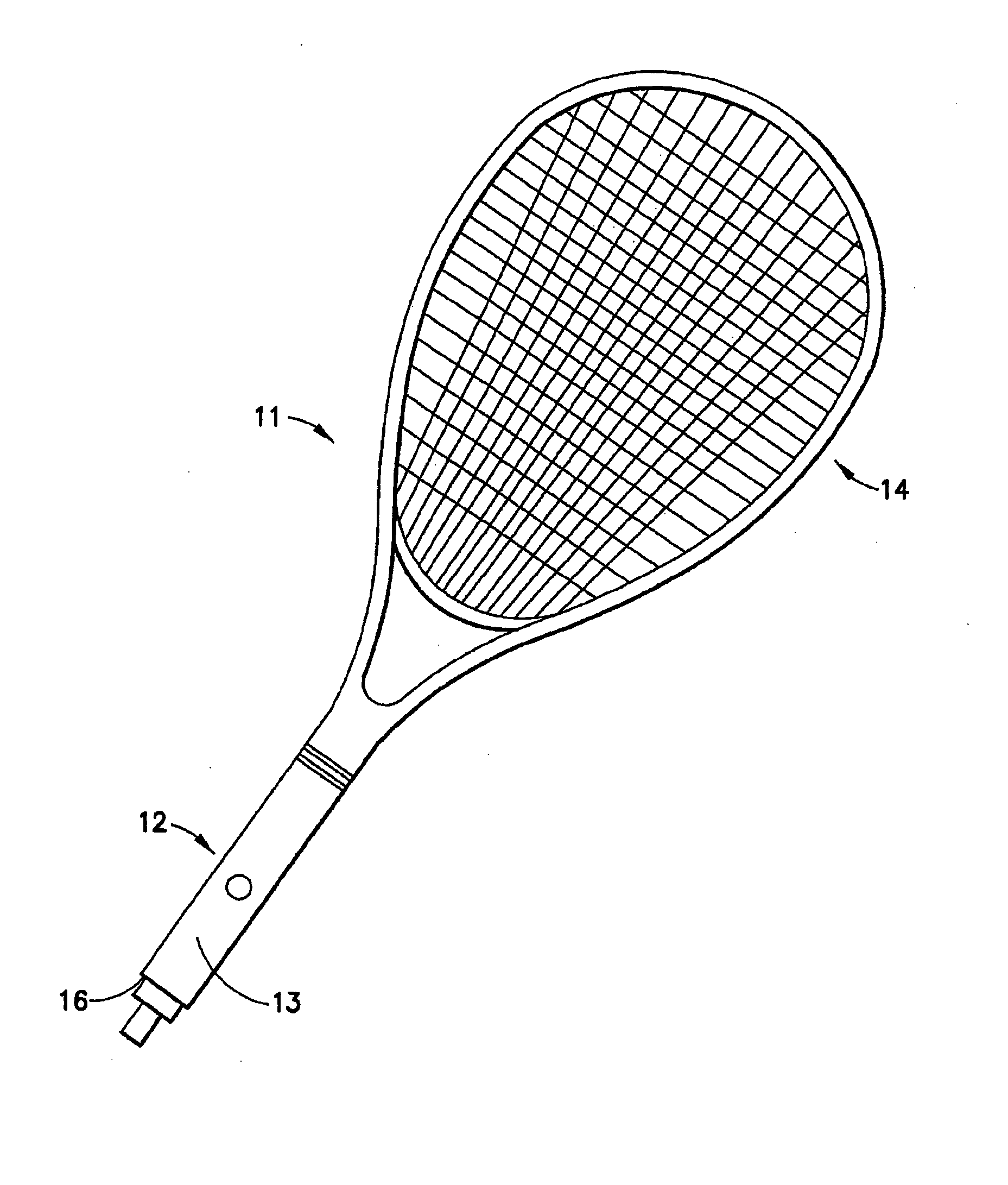
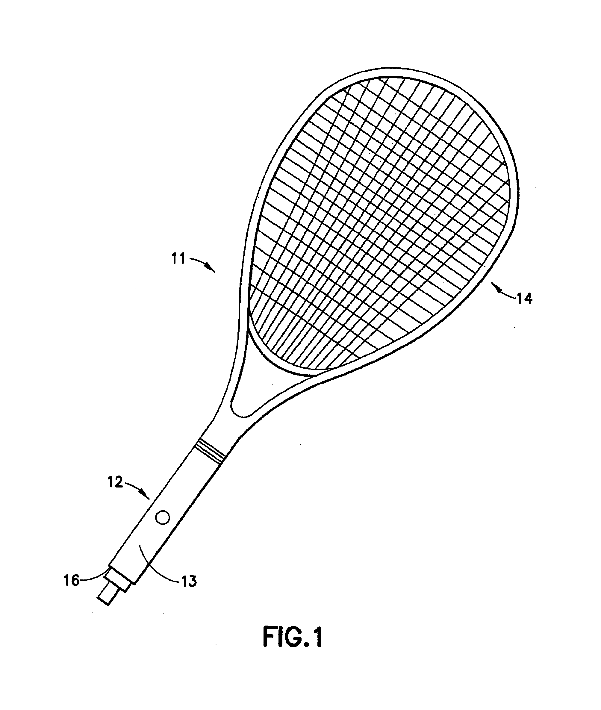
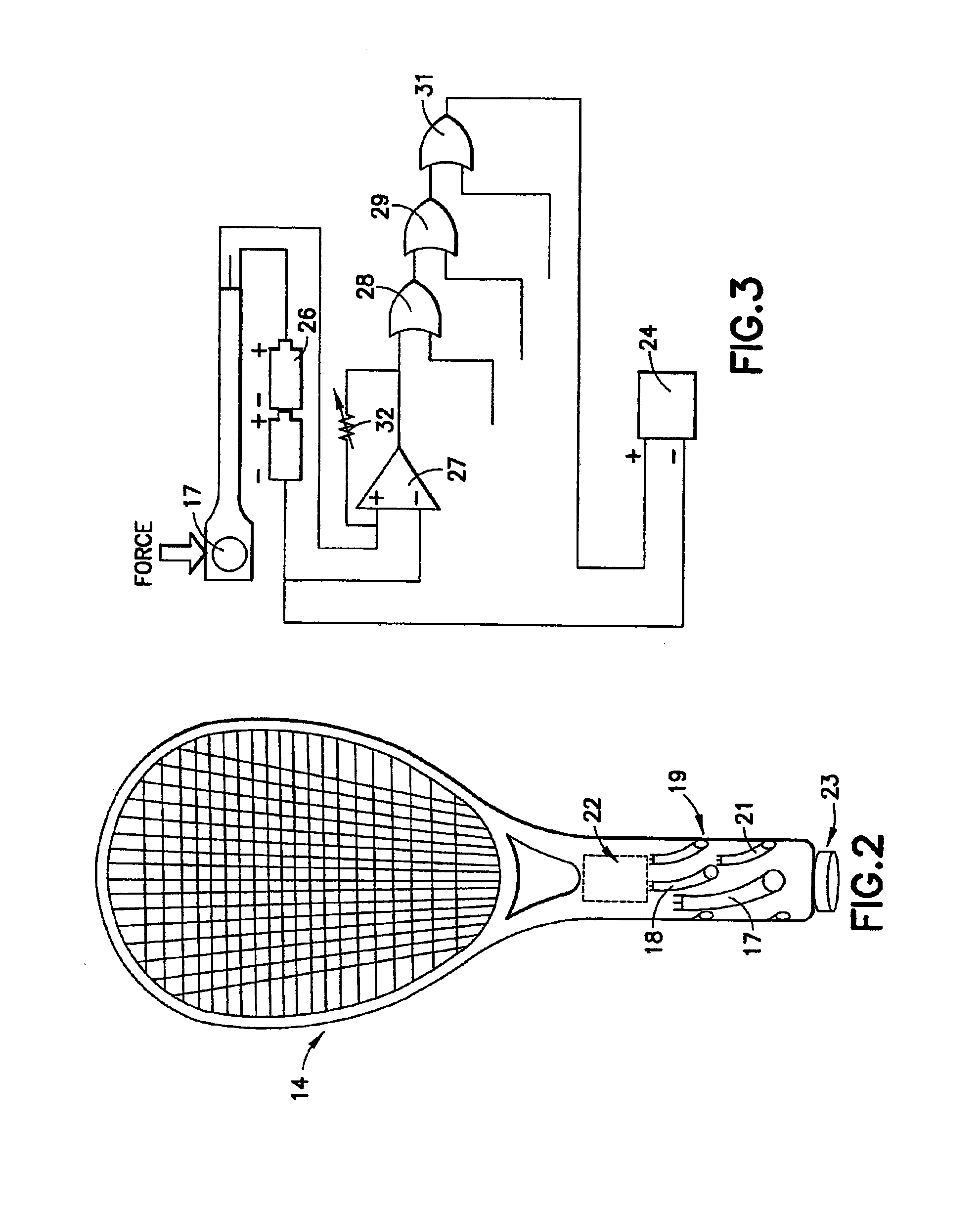
[0027]The first design, as shown in FIG. 1, is comprised of a tennis racket 11 having a handle 12 with a grip handle 13 and a racket head 15. The handle 12 includes a grip sensor 16. The details of grip sensor 16 are shown in FIG. 2. Grip sensor 16 includes a pattern of piezoelectric force sensors 17, 18, 19 and 21 placed within the grip handle 13 together with an electrical circuit 22. Handle 12 also includes a sensitivity adjustment knob 23 operatively connected to electrical circuit 22.

[0028]The grip sensor 16 alerts a playe...


PUM


Abstract

A sports training device that includes a pressure sensor mounted on the hand grip of a sports implement such as a tennis racket or a golf club. The device utilizes a piezoelectric force sensor to monitor the grip pressure in a circular sensing area located where the palm meets the index finger. The piezoelectric sensor varies its resistance inversely with the force applied and is connected to an operational amplifier that uses a variable resistor to deliver an output voltage proportional to the force applied. This voltage triggers a vibrating motor that alerts the user that an excessive pressure has been applied to the hand grip. The exact amount of pressure for each player and the sports equipment used will vary but can be adjusted to signal when the pressure is too great for the particular use.

Description


Claims


Application Information

Patent Timeline
Owner KAUFMAN ALEXANDER
Why Eureka
Try Eureka