Expandable shield instrument for use in intraocular surgery

a shield instrument and expandable technology, applied in the field of expandable shield instruments for intraocular surgery, can solve the problems of increased risk of posterior segment complications and continuing inflammation, increased risk of vitreous hemorrhage, and increased risk of vitreous disruption, retinal tear, and vitreous hemorrhag

Active Publication Date: 2013-05-28
NEVYAS WALLACE ANITA +1
View PDF9 Cites 2 Cited by
  • Summary
  • Abstract
  • Description
  • Claims
  • Application Information

AI Technical Summary

Benefits of technology

[0007]The present invention provides an instrument capable of providing large-area shielding within the eye, while being passable through a small incision through which the instrument must be inserted into the eye. More specifically, the present invention provides an instrument capable of being passed through a typical 3 mm (or smaller) phacoemulsification incision without undue damage to ocular tissue, and which expands to provide large-area shielding, e.g. to occlude a large-diameter (e.g. approx. 6 mm) posterior capsule opening.

Problems solved by technology

Such rupture carries with it the risk of posterior segment complications and continuing inflammation if cortical and nuclear material released during phacoemulsification of the lens descends to the posterior compartment.
Retention of lens material posteriorly also may necessitate subsequent posterior compartment surgery, with its attendant inconvenience and risk.
Accordingly, the portion of the lens guide positioned intraocularly cannot effectively prevent lens material from descending to the posterior compartment; phacoemulsified lens material may easily pass beside and behind the 3 mm (or smaller) wide lens guide.
Viscoelastic material does not present a solid barrier to posterior migration of lens material, and any technique requiring creating and placing instruments through a pars plana incision entails additional risk of vitreous disruption, retinal tear, choroidal hemorrhage, and vitreous hemorrhage.
Furthermore, such techniques do not provide a barrier to prevent substantial loss of lens material backward into the posterior compartment, especially if the pupil is larger than 3 mm in diameter.

Method used


Image

  • Expandable shield instrument for use in intraocular surgery
  • Expandable shield instrument for use in intraocular surgery
  • Expandable shield instrument for use in intraocular surgery

Examples


Embodiment Construction

[0022]The present invention provides an instrument capable of providing large-area shielding within the eye, e.g. a shielding surface having an approximate maximum length and maximum width each greater than 3 mm, and / or providing a shielding area greater than approximately 9 mm2′ and preferably greater than approximately 5 mm in diameter and / or greater than approximately 19 mm2. The instrument is specially-configured to provide such large-area shielding and yet to be passable through a small slit-like incision, e.g. 3 mm or less in width, through which the instrument must be inserted into the eye during ocular surgery.

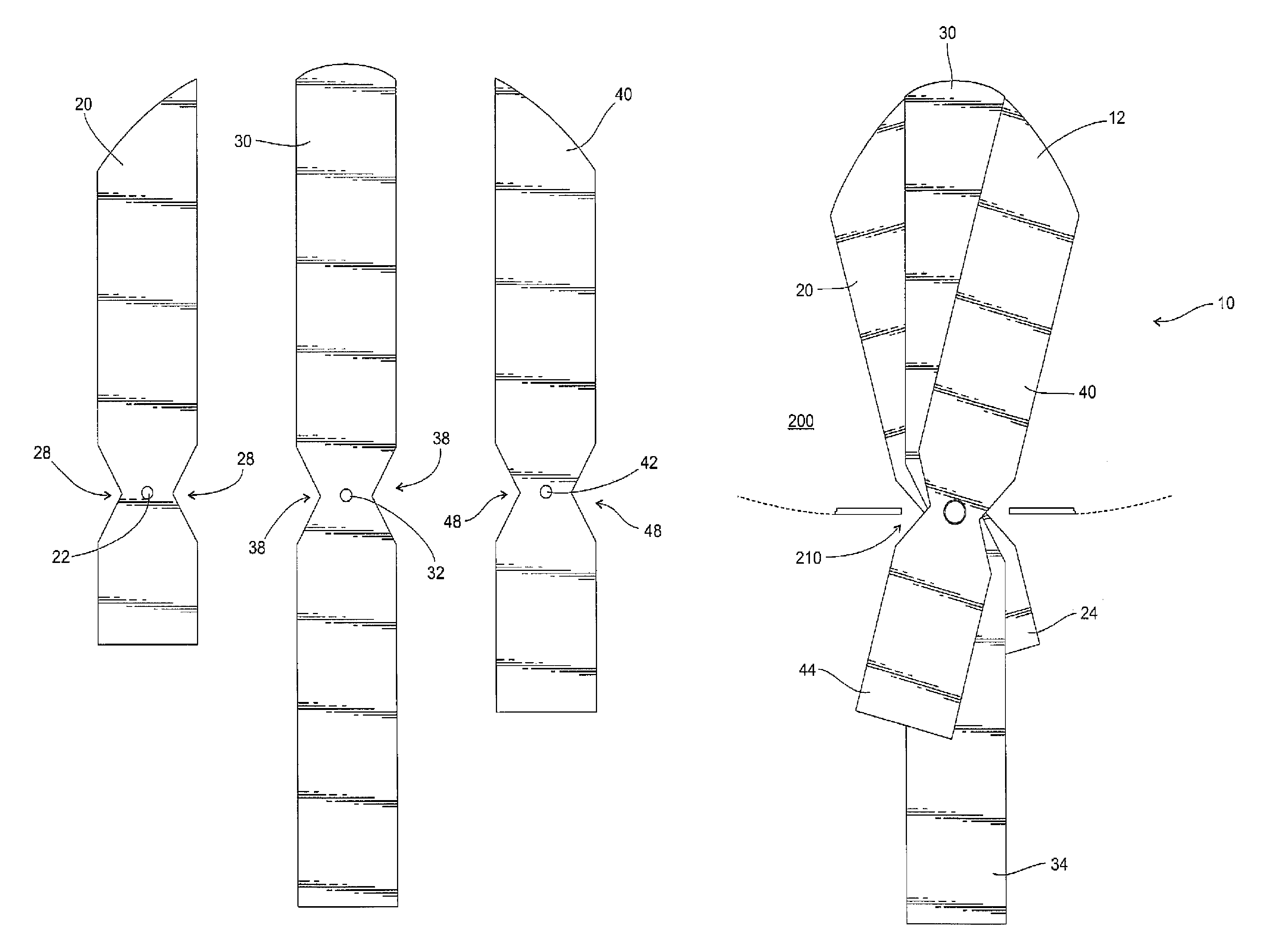
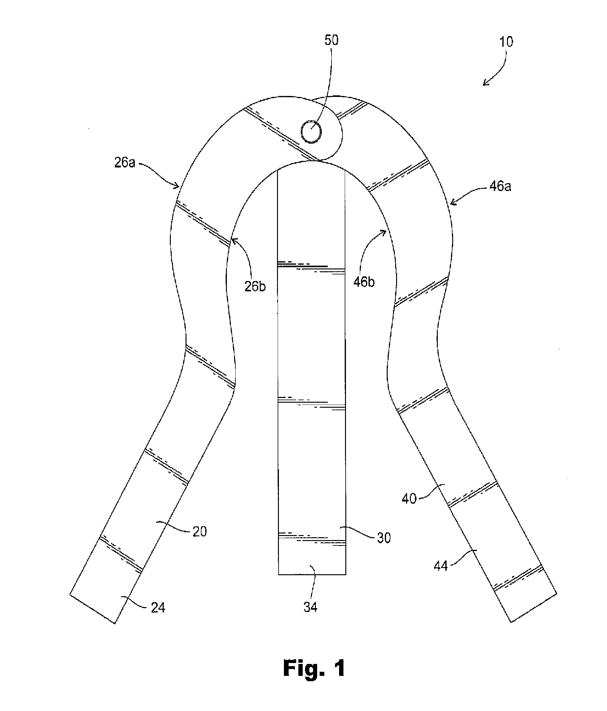
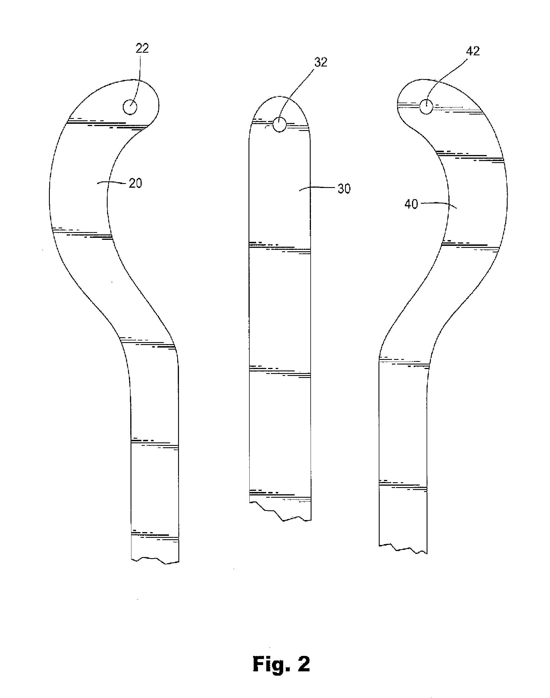
[0023]FIGS. 1-6 show an exemplary expandable shield instrument 10. As shown in FIGS. 1 and 2, this exemplary instrument includes three leaves 20, 30, 40 fixedly joined to one another, but in a manner permitting relative rotational movement of the leaves. In this embodiment, each of the leaves defines an opening 22, 32, 42 toward its respective distal end to allow for i...


PUM


Abstract

An instrument capable of providing large-area shielding within an isolated operating region, such as the eye, while being passable through a small incision in the region through which the instrument must be inserted. For example, an instrument capable of being passed through a typical 3 mm (or smaller) phacoemulsification incision without undue damage to ocular tissue, and which expands to provide large-area shielding, e.g. to occlude a large-diameter (e.g. approx. 6 mm) posterior capsule opening. The surgical instrument includes two or more leaves, the leaves being interconnected by at least one fastener in a manner that causes expansion of a leading or distal portion of the instrument when the following or proximal portions of each leaf are manipulated, whether by a user or through interaction with a wall of the incision.

Description

CROSS REFERENCE TO RELATED APPLICATIONS[0001]This application claims the priority of PCT / US2008 / 078753, filed on Oct. 3, 2008, which is based on and claims priority to U.S. Provisional Application No. 60 / 977,867, filed Oct. 5, 2007, the entire contents of which are hereby incorporated fully herein by reference.FIELD OF THE INVENTION[0002]The present invention relates generally to instruments for use in intraocular surgery, and more particularly to an instrument capable of providing large-area shielding within the eye, yet being passable through a small incision into the eye.DISCUSSION OF RELATED ART[0003]Various surgical procedures involve placement of instruments through an incision made in ocular tissue. Exemplary surgical procedures include a phacoemulsification procedure in which a small incision is made in the cornea by a keratome or similar flat-bladed knife. The incision is necessary to permit insertion of instruments into the eye, and to provide access to inner portions of t...

Claims


Application Information

Patent Timeline
Patent Type & Authority Patents(United States)
IPC IPC(8): A61M29/00
CPCA61B19/24A61F9/007A61B17/3423A61B2019/4036A61B2019/481A61B2090/0436A61B90/02A61B2090/08021
Inventor NEVYAS-WALLACE, ANITAWALLACE, BENJAMIN
Owner NEVYAS WALLACE ANITA
Why Eureka
Try Eureka