Closed-end welding electrode holder

a closed-end, electrode-holder technology, applied in the direction of electrode supporting devices, non-shielding electrode holders, manufacturing tools, etc., can solve the problems of reducing efficiency, welding projects, and losing the grip of the electrode, so as to prevent the inherent gripping problem, facilitate the bending of the electrode, and tighten the clamping on the electrode

Active Publication Date: 2013-05-28
LANGLEY CHARLES MARK
View PDF25 Cites 2 Cited by
  • Summary
  • Abstract
  • Description
  • Claims
  • Application Information

AI Technical Summary

Benefits of technology

[0010]The present invention overcomes the disadvantages and limitations of the prior art by providing an electrode holder with a closed-end structure that prevents the gripping problems inherent with open-jawed electrode holders, is made of a stronger metal than copper, and contains a V-shaped hole that allows tighter clamping of an electrode and eases the process of bending an electrode by hand. This electrode holder also has a comfortable handle covered by a sleeve that keeps the electrode holder cool to the touch and allows a welding lead to be fed through the handle and connected to the electrode holder without removing the handle of the electrode holder.
[0011]The present invention may thus comprise a closed-jaw welding electrode holder that offers a tighter grip on welding electrodes, offers improved durability and extended life, allows easier replacement of old welding electrodes, and allows easier bending of welding electrodes, comprising: a head with a closed end that is made of a metal with high thermal conductivity; at least one insert within the head that is harder than the material of the head and creates a V-shaped hole within the head; a jaw that may move back and forth within a slot to bisect the V-shaped hole and allow tight gripping of a welding electrode; a body that attaches to the head; a spring fastened between the jaw and the body that governs the relative movement of the jaw with respect to the body; a sleeve that tightly encloses the body of the welding electrode holder, contains an opening to accommodate a welding lead, and improves a user's grip on the welding electrode holder; a lug that attaches a welding lead to the body; a hole in the body that can accommodate a fastener; and a fastener that fits into the hole in the body and attaches the lug, the welding lead and the body together.
[0013]The advantages of the present invention are the closed-end structure of the electrode holder that prevents the gripping problems inherent with open-jawed electrode holders, the V-shaped hole that allows tighter clamping onto an electrode, the consequent ease of bending an electrode by hand when compared with open-jawed holders, and the ease of replacing old electrodes.

Problems solved by technology

Other electrode holders may use a “pistol grip” that securely grips an electrode but requires two hands to remove a used electrode and insert a new one, thus reducing efficiency.
The stiffness of the electrode and the brute strength needed to make it bend often cause either the electrode to pop out of the tongs or the tongs to be pried open and thus lose their grip on the electrode.
Once tongs have been bent, a welder must exercise constant care to ensure that an electrode remains tightly gripped, as even slight movement of an electrode within the tongs may severely damage a welding project.
During welding projects where a welder uses hundreds of electrodes (and bends many of them by hand) per day, a copper tong-type electrode holder may require replacement every 2-4 weeks because it can no longer grip an electrode tightly enough to allow efficient and accurate welding.
The bending process may also injure or cause permanent damage to the wrists of a welder because of the brute strength needed for bending.
U.S. Pat. No. 2,806,126 (Gladen) adds grooves to tongs to help them grip an electrode more tightly, but even grooves cannot give an open-jawed electrode holder sufficient gripping strength to withstand constant electrode bending.
Another problem with many tong-type holders is that over time, their metal content may make them too hot to hold properly because of the extreme temperatures generated during welding.

Method used


Image

  • Closed-end welding electrode holder
  • Closed-end welding electrode holder
  • Closed-end welding electrode holder

Examples


Embodiment Construction

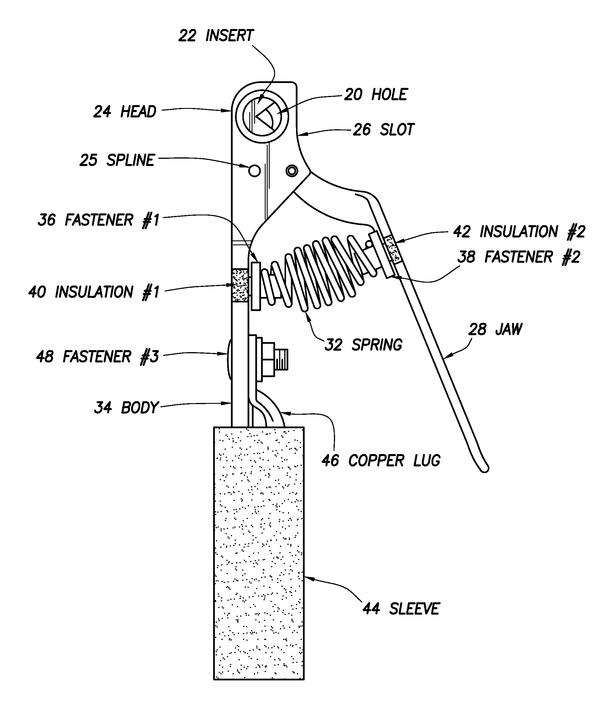
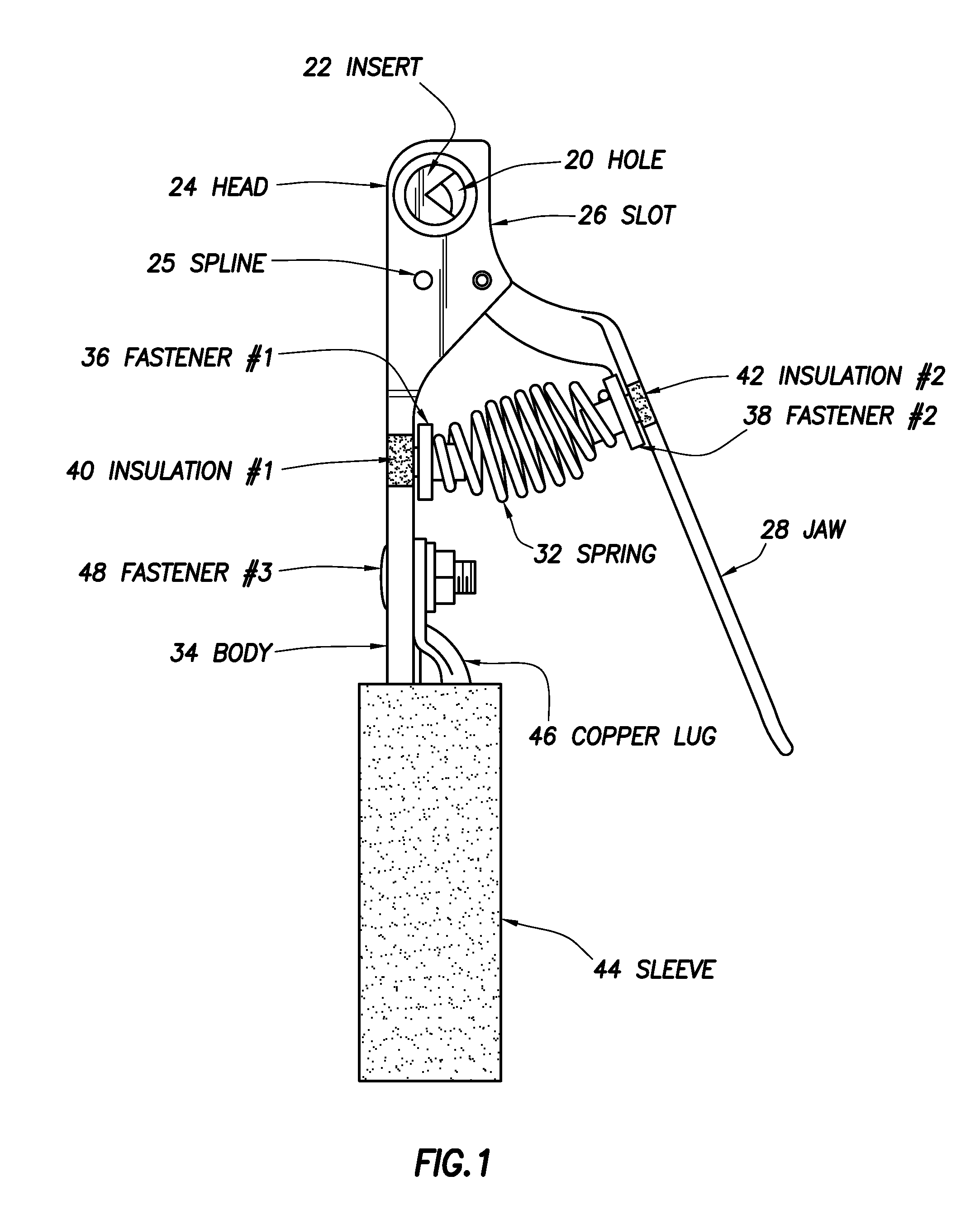
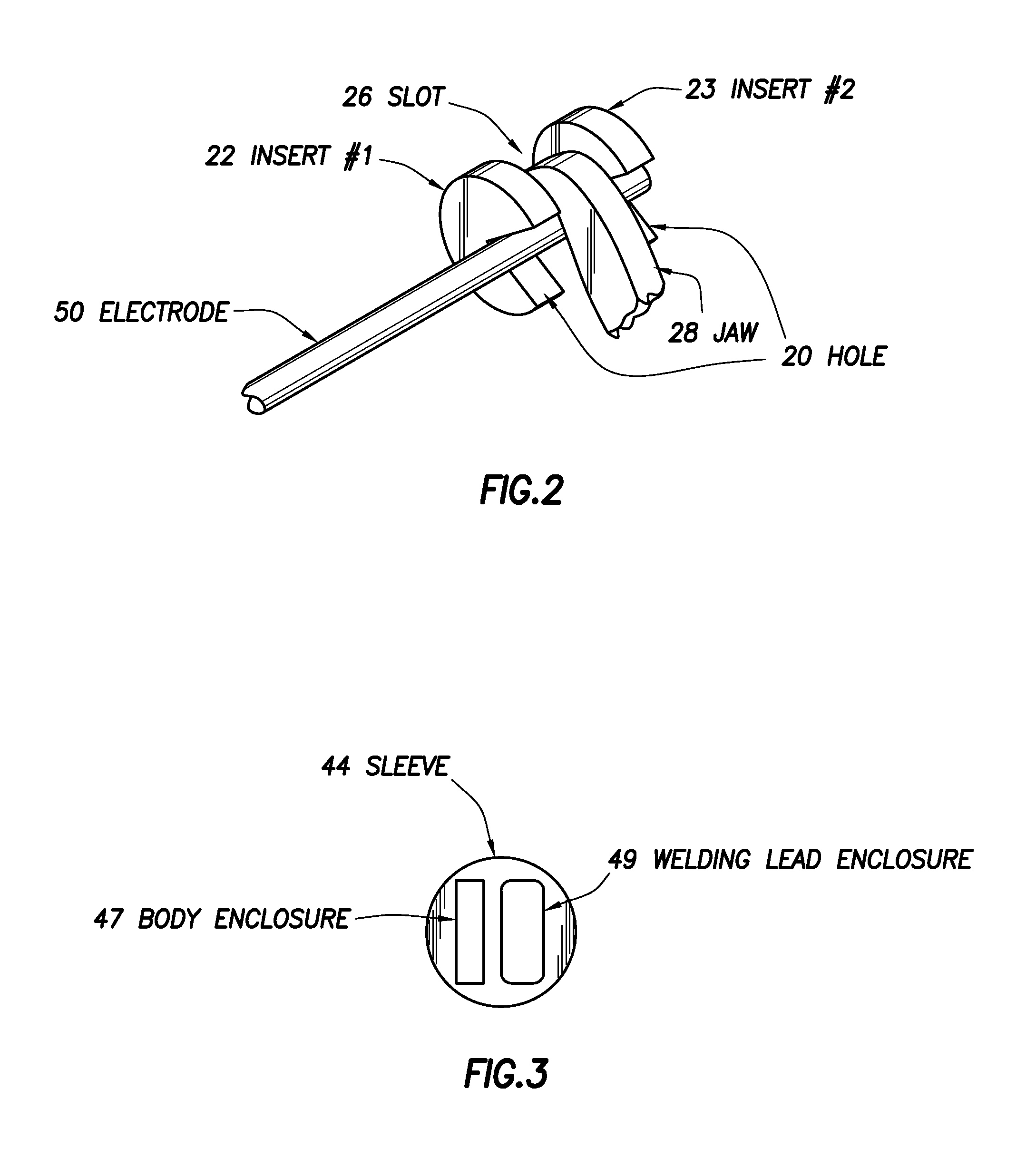
[0019]FIG. 1 illustrates a schematic representation of the various elements of the present invention, which holds an arc-welding electrode in place when the electrode is inserted into a hole 20 that may be created by an insert 22. The hole 20 may extend through the entire width of a head 24 and may be bisected along its length by a slot 26 that may contain a jaw 28 that may have an attached spring 32 and may be made of one or more pieces. The spring 32 may be connected between a body 34 and the jaw 28 by means of fastener #136 and fastener #238. Fastener #136 and fastener #238 may be covered by insulation #140 and insulation #242. The bottom of the body 34 may be sheathed by a sleeve 44. A copper lug 46, typically used to secure a welding lead during welding, may be fastened to the body 34 by a fastener #348.

[0020]The hole 20 may have an external shape that looks like the letter V may have an internal shape that look like a V, and may create a deep groove that allows for a more secu...


PUM

PropertyMeasurementUnit
interior angleaaaaaaaaaa

Abstract

Disclosed is an electrode holder to be used in welding that has a closed-end structure that removes the gripping problems inherent with open-jawed “tong-type” electrode holders. The electrode holder contains a grooved hole that allows tighter clamping onto an electrode, easing the process of bending an electrode by hand. The electrode holder also has a comfortable handle covered by a sleeve that keeps the electrode holder cool to the touch, allowing a welding lead to be fed through the sleeve and connected to the electrode holder without removing the handle of the electrode holder.

Description

CROSS REFERENCE TO RELATED APPLICATIONS[0001]The present invention claims the benefit of U.S. Provisional Application Ser. No. 60 / 998,394, filed 27 Nov. 2007, entitled “A Tool For Firmly Holding Welding Electrodes” by Charles Mark Langley.BACKGROUND OF THE INVENTION[0002]a. Field of the Invention[0003]The present invention generally pertains to arc welding and more particularly to electrode holders used during arc welding.[0004]b. Description of the Background[0005]Many arc welders use electrode holders to keep an electrode in a fixed position while welding and allow the metal in the electrode to fill the weld. Typical copper electrode holders are “tong-type” that grip an electrode between a pair of openable jaws or “tongs”; in some cases, the tightness of the tongs may be adjustable by a screw or spring. Other electrode holders may use a “pistol grip” that securely grips an electrode but requires two hands to remove a used electrode and insert a new one, thus reducing efficiency.[0...

Claims


Application Information

Patent Timeline
Patent Type & Authority Patents(United States)
IPC IPC(8): B23K9/28
CPCB23K9/282
Inventor LANGLEY, CHARLES MARK
Owner LANGLEY CHARLES MARK
Why Eureka
Try Eureka