Radio-frequency (RF) amplifier circuits and related techniques

a technology of amplifier circuit and radio frequency, applied in the field of radio frequency amplifiers, can solve the problems of high cost, high cost, and high cost, and achieve the effect of small output power and reduced losses

Active Publication Date: 2013-05-28
MASSACHUSETTS INST OF TECH
View PDF11 Cites 65 Cited by
  • Summary
  • Abstract
  • Description
  • Claims
  • Application Information

AI Technical Summary

Benefits of technology

[0026]In one embodiment, the RF system further includes a drain modulation circuit coupled to each of the power amplifier circuits. In one embodiment, the drain modulation circuit includes one or more of: an adaptive bias circuit, a polar modulation circuit, a discrete drain switching circuit. In one embodiment, the drain modulation circuit operates in accordance with an asymmetric multilevel outphasing technique. In one embodiment, the drain modulation circuit implements gate-width switching of the power amplifiers to reduce losses at small output powers.

Problems solved by technology

This becomes particularly challenging when wide-bandwidth control of an output signal is required.
Simultaneously achieving both of these requirements—wide-bandwidth linear amplification and high average efficiency—has been a longstanding challenge.
One important consideration with outphasing is how the power combining is done, particularly because many high-efficiency power amplifiers are highly sensitive to load impedance, and their performance and efficiency can heavily degrade due to interactions between the power amplifiers.
This leads to a rapid degradation of efficiency as output power is decreased, diminishing the attractiveness of this approach.
However, the reactive portions of the effective load admittances (Yin,1, Yin,2) are only zero at two outphasing angles, and become large outside of a limited power range (see the example plots in FIG. 3).
This limits efficiency, due both to loss associated with added reactive currents and to degradation of power amplifier performance with (variable) reactive loading.
However, because the effective reactive loading due to PA interactions depends upon operating point (outphasing angle), compensation is imperfect over most of the operating range.
This can thus lead to loss of efficiency and PA degradation when operating over wide ranges.

Method used


Image

  • Radio-frequency (RF) amplifier circuits and related techniques
  • Radio-frequency (RF) amplifier circuits and related techniques
  • Radio-frequency (RF) amplifier circuits and related techniques

Examples


Embodiment Construction

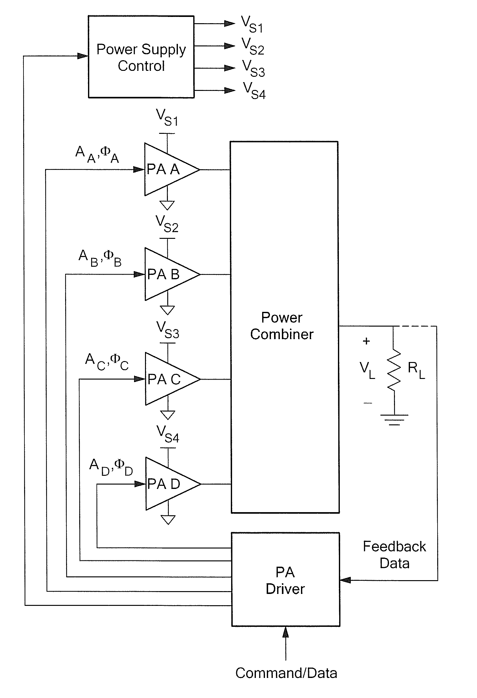
[0091]Referring now to FIG. 4, while conventional outphasing systems utilize two power amplifiers, a system configured in accordance with the concepts and techniques described herein combines power from four or more amplifiers. It should be appreciated that the power combiner is substantially lossless, and enables output power to be controlled by the relative phasing of the individual power amplifiers, while providing desirable input impedances at the power combiner inputs. It should also be appreciated that for a specified load resistance RL, controlling output power P is equivalent to controlling the output voltage amplitude, since P=Vout2 / (2RL). It should also be noted that power may additionally be controlled through other methods, including amplitude modulation of the power amplifier inputs and modulation of the power supply / supplies of the power amplifiers (i.e. other techniques may be used in combination with outphasing techniques described herein).

[0092]It should also be app...


PUM


Abstract

A power combining and outphasing system and related techniques for simultaneously providing both wide-bandwidth linear amplification and high average efficiency is described. Providing linear amplification encompasses the ability to dynamically control an RF output power level over a wide range while still operating over a wide frequency bandwidth. The system and techniques described herein also operate to maintain high efficiency across a wide range of output power levels, such that a high average efficiency can be achieved for highly modulated output waveforms.

Description

CROSS REFERENCE TO RELATED APPLICATIONS[0001]This application claims the benefit under 35 U.S.C. §119(e) of provisional application No. 61 / 300,963 filed on Feb. 3, 2010 which application is hereby incorporated herein by reference in its entirety.STATEMENT REGARDING FEDERALLY SPONSORED RESEARCH[0002]Not Applicable.FIELD OF THE INVENTION[0003]The concepts described herein relate to radio frequency (RF) amplifiers, and more particularly to power combining and outphasing modulation systems and techniques.BACKGROUND OF THE INVENTION[0004]As is known in the art, radio-frequency (RF) power amplifiers (PAs) are important in numerous applications, including RF communications, medical imaging, industrial heating and processing, and dc-dc power conversion among many others. PAs are often required to provide linear amplification, which encompasses the ability to dynamically control an RF output power over a wide range. This becomes particularly challenging when wide-bandwidth control of an outp...

Claims


Application Information

Patent Timeline
Patent Type & Authority Patents(United States)
IPC IPC(8): H03F3/68
CPCH03F1/0294H03F3/602H03F1/56
Inventor PERREAULT, DAVID J.JURKOV, ALEXANDER S.
Owner MASSACHUSETTS INST OF TECH
Why Eureka
Try Eureka