Tool to automatically align outdoor unit

a technology of automatic alignment and outdoor unit, which is applied in the direction of antenna details, antennas, electrical devices, etc., can solve the problems of insufficient accuracy of current alignment techniques and odu designs, and useless information transmitted in downlink signals, and achieve the effect of maximizing signal strength

Active Publication Date: 2013-05-28
DIRECTV LLC
View PDF13 Cites 20 Cited by
  • Summary
  • Abstract
  • Description
  • Claims
  • Application Information

AI Technical Summary

Benefits of technology

[0022]A method for aligning an antenna to a satellite configuration in accordance with one or more embodiments of the present invention comprises coupling a meter to an output of the antenna, measuring a signal strength from the output of the antenna, coarsely aligning the antenna in azimuth and elevation, coupling a motor to at least one fine alignment mechanism of the antenna, and adjusting the fine alignment mechanism with the motor, wherein the motor is moved based on the signal strength received from the output of the antenna such that signal strength is maximized using the fine alignment mechanism.

Problems solved by technology

However, as mentioned above, current IRDs 112 cannot use the information in some of the proposed frequencies used for downlink signals 120, thus rendering useless the information transmitted in those downlink signals 120.
However, current alignment techniques and ODU designs are not accurate enough for such alignments.

Method used


Image

  • Tool to automatically align outdoor unit
  • Tool to automatically align outdoor unit
  • Tool to automatically align outdoor unit

Examples


Embodiment Construction

[0032]In the following description, reference is made to the accompanying drawings which form a part hereof, and which show, by way of illustration, several embodiments of the present invention. It is understood that other embodiments may be utilized and structural changes may be made without departing from the scope of the present invention.

Overview

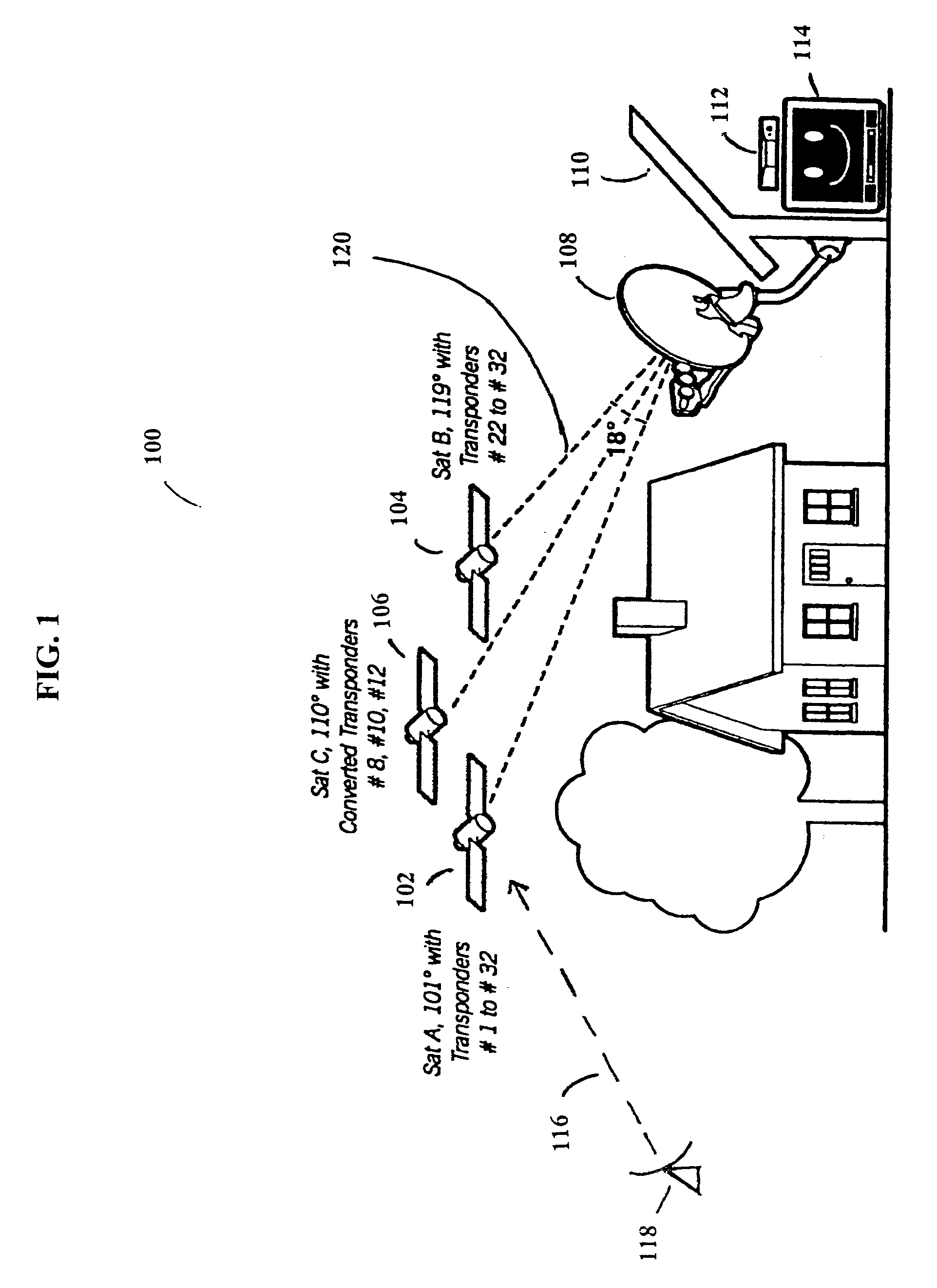
[0033]Currently, there are several orbital slots, each comprising one or more satellites, delivering direct-broadcast television programming signals to the various ODUs 108. However, ground systems that currently receive these signals sometimes cannot accommodate additional satellite signals without adding more cables, and cannot process the additional signals that will be used to transmit the growing complement of high-definition television (HDTV) signals. The HDTV signals can be broadcast from the existing satellite constellation, or broadcast from the additional satellite(s) that will be placed in geosynchronous orbit. The orbital loc...


PUM


Abstract

An alignment tool for aligning an antenna to a satellite configuration and a method for aligning an antenna to a satellite configuration is disclosed. An alignment tool for aligning an antenna to a satellite configuration in accordance with the present invention comprises a meter for measuring a satellite downlink signal power from the antenna, a motor for adjusting at least one fine adjustment mechanism of the antenna, and a processor, coupled to the motor and to the meter, for commanding the motor based on the received power from the antenna, wherein the processor commands the motor to maximize a received power from the antenna.

Description

BACKGROUND OF THE INVENTION[0001]1. Field of the Invention[0002]The present invention relates generally to a satellite receiver system, and in particular, to an antenna assembly for such a satellite receiver system.[0003]2. Description of the Related Art[0004]Satellite broadcasting of communications signals has become commonplace. Satellite distribution of commercial signals for use in television programming currently utilizes multiple feedhorns on a single Outdoor Unit (ODU) which supply signals to up to eight Integrated Receiver Decoders (IRDs) on separate cables from a multiswitch.[0005]FIG. 1 illustrates a typical satellite television installation of the related art.[0006]System 100 is an embodiment that uses signals sent from Satellite A (SatA) 102, Satellite B (SatB) 104, and Satellite C (SatC) 106 (with transponders 28, 30, and 32 converted to transponders 8, 10, and 12, respectively), that are directly broadcast to an Outdoor Unit (ODU) 108 that is typically attached to the ...

Claims


Application Information

Patent Timeline
Patent Type & Authority Patents(United States)
IPC IPC(8): H01Q1/12
CPCH01Q1/1221H01Q19/17
Inventor SANTORU, JOSEPH
Owner DIRECTV LLC
Why Eureka
Try Eureka