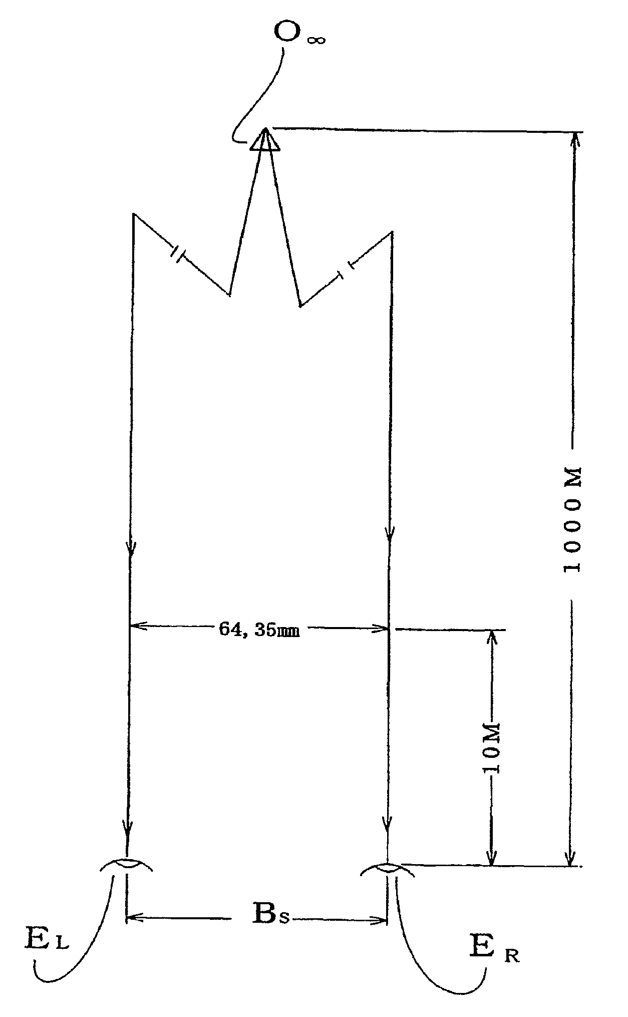
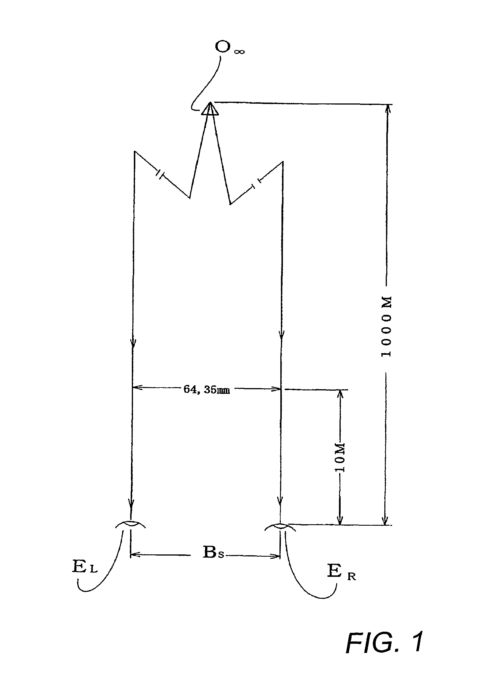
[0016]According to this configuration, a state of an optimal stereoscopic effect can be reproduced by displaying images for right and left in such a superimposing manner that the centers of the images coincide with each other and displaying a distance between the same corresponding points of right and left images of a subject positioned at an infinite distance to be equal to an interpupillary distance of a human.
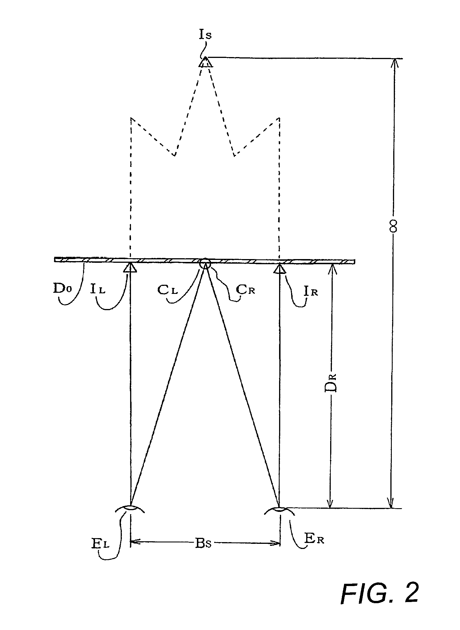
[0018]According to this configuration, the invention in another embodiment is applied to a stereoscopic television using a display with a width narrower than the reference size, whereby one portions (end portions) of the respective display screens for right and left are concealed (displayed in black), display is performed such that the centers of the display screens for right and left are separated from each other, the right and left viewing fields are caused to coincide with each other behind the position of the display, and display is simultaneously performed such that a distance between the same corresponding points of the right and left images of an infinite subject is equal to an interpupillary distance of a human, so that, though a viewer watches a television with a small screen size, an effect equivalent to a state that he / she watches a stereoscopic television having a display with the reference size from the recommended viewing distance can be obtained.
[0020]According to the configuration, the invention in another embodiment is applied to a stereoscopic television using a display with a width wider than the reference size, where portions (end portions) of the respective screens for the right and the left are concealed (displayed in black) symmetrically so that display is performed such that the widthwise centers of the respective display screens for right and left are moved in directions of coming close to each other until they switch positions with each other (the center of the screen for left is moved rightward while the center of the screen for right is moved leftward), thereby causing the right and left viewing field to coincide with each other before the display, and simultaneously the distance between the right and the left of the corresponding point on an infinite subject image is displayed to be equal to an interpupillary distance of a human so that an effect similar to a state that a viewer watches a stereoscopic television having a display with a reference size from a recommended viewing distance. This invention is configured such that a viewer watches a stereoscopic television from a distance farther than the recommended viewing distance applied when a viewer watches a stereoscopic television with a reference size, and a characteristic thereof lies in that a space between a television and a viewer can be set largely. Accordingly, the present invention in this embodiment is effective when many persons or viewers watch television at the same time.
[0022]According to the configuration, especially, in glasses for field separation for separating images for right and left of a stereoscopic image of a system performing display on an LCD panel in a time-division manner, where polarizing directions of light beams passing through the right and left liquid crystal plates of the glasses are arranged so as to be orthogonal to each other in time sequence by alternately applying a voltage to the right and left liquid crystal plates provided on the front face of the glasses and polarized lights orthogonal to each other are detected by the polarizing plates disposed behind the liquid crystal plates of the glasses so that even if a viewer inclines his / her glasses (head), the inclination angle is detected by the inclination angle sensor provided on the glasses and a voltage applied to the liquid crystal plates is controlled to prevent crosstalk.
[0023]When a distance between the same corresponding points of right and left images of an infinite subject is displayed to be equal to an interpupillary distance of a human in a stereoscopic television, an infinite image is prevented from appearing at a position at a near distance and a distance feeling of the infinite image is prevented from collapsing even if a viewing distance varies.
[0025]In two eyes stereoscopic viewing, recently, a circularly-polarizing filter is frequently used for the polarizing glasses for separating right and left viewing fields in order to prevent crosstalk. A problem of the circularly-polarizing plate lies in its high price. Further, because a quarter wavelength plate is used, bias occurs in wavelength of light passing through the plate. Recently, a television of an LCD system has been screen-enlarged and has been subjected to high definition. Since light beam emitted from an LCD panel is polarized light (linearly-polarized light), separation of right and left viewing fields can be made relatively easy by utilizing the polarized light. However, crosstalk may occur in the linearly-polarized light when the glasses are inclined to the display. This problem can be easily solved by attaching an inclination angle sensor to the glasses and controlling a voltage to be applied to liquid crystal plates arranged on the front face of the polarizing glasses.

