Locking mechanism and an optical disk drive having the same

a technology of optical disk drive and locking mechanism, which is applied in the direction of recording information storage, record carrier contruction details, instruments, etc., can solve the problems of consuming more assembly time, affecting the operation and suddenly stopping the reading of the optical disk drive or becoming damaged, so as to achieve the effect of simple structure and effective minimization of assembly time and production costs

Inactive Publication Date: 2013-05-28
WISTRON CORP
View PDF4 Cites 0 Cited by
  • Summary
  • Abstract
  • Description
  • Claims
  • Application Information

AI Technical Summary

Benefits of technology

[0008]A main object of the present invention is to provide a locking mechanism having a safety lock function to prevent accidental operation thereof and that has a simple structure which can minimize assembly time and production costs.
[0009]Another object of the present invention is to provide an optical disk drive having a locking mechanism. The locking mechanism having a safety lock function to prevent accidental operation thereof and that has a simple structure which can minimize assembly time and production costs.
[0012]Through the aforesaid technical means, the advantages and effectiveness of the optical disk drive having the locking mechanism according to the present invention reside in the fact that through the configuration of the locking element of the locking mechanism which is movable between a non-operative position and an operative position, a safety lock function is provided. Further, since the locking mechanism has few components and a simple structure, the assembly time and the production costs thereof can be effectively minimized.

Problems solved by technology

However, this kind of structure easily results in ejection of the tray due to accidental touching of the button by a user or through the presence of an external force, so that, during reading of optical disk data by the optical disk drive, the optical disk drive suddenly stops reading or become damaged when the tray is bumped.
However, the ejection mechanism of the aforesaid patent has numerous components, and the structure thereof is complicated.
Hence, it consumes more assembly time, and has high production costs.

Method used


Image

  • Locking mechanism and an optical disk drive having the same
  • Locking mechanism and an optical disk drive having the same
  • Locking mechanism and an optical disk drive having the same

Examples


Embodiment Construction

[0024]The above-mentioned and other technical contents, features, and effects of this invention will be clearly presented from the following detailed description of the embodiment in coordination with the reference drawings. Through description of the concrete implementation method, the technical means employed and the effectiveness to achieve the predetermined purposes of the present invention will be thoroughly and concretely understood. However, the enclosed drawings are used for reference and description only, and are not used for limiting the present invention.

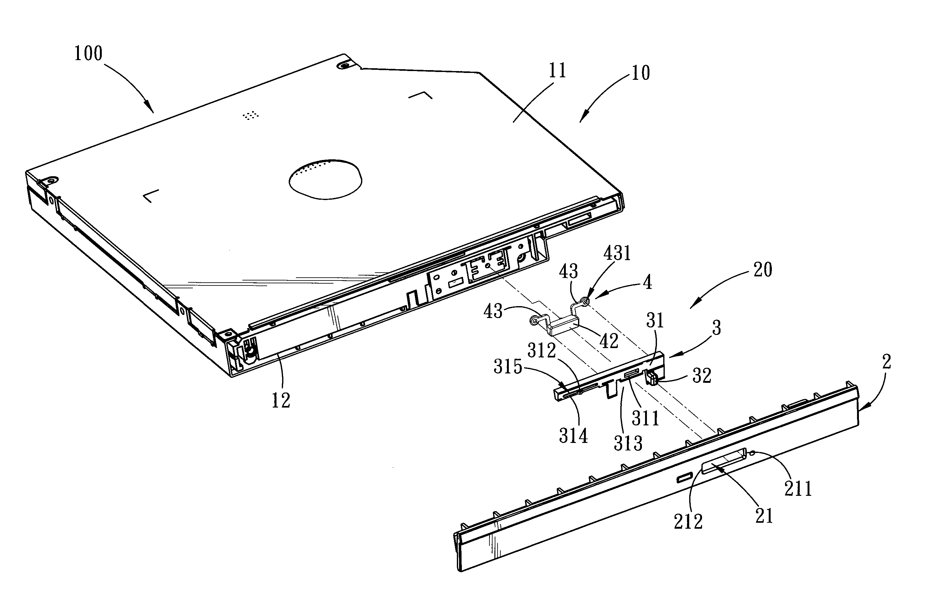
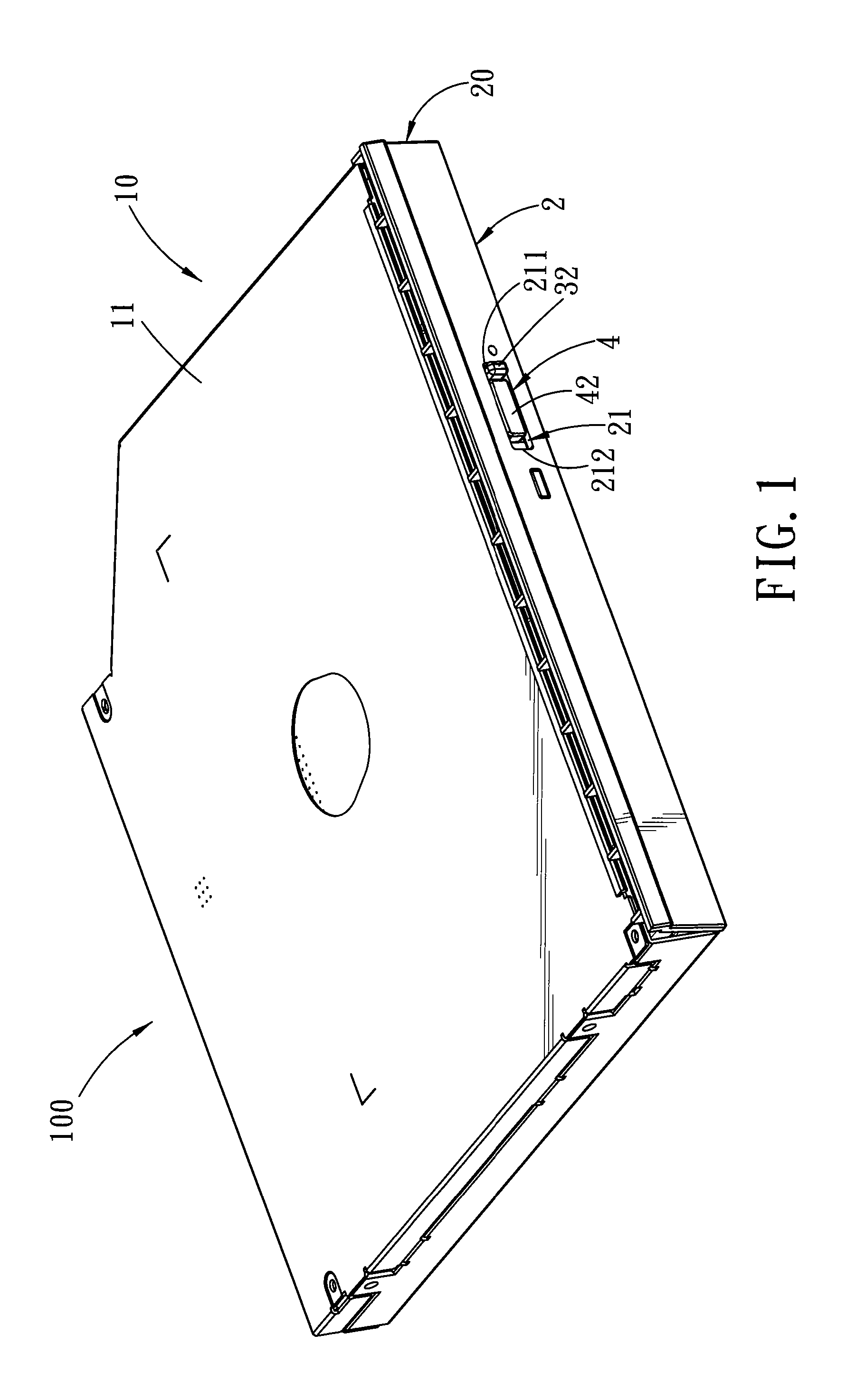
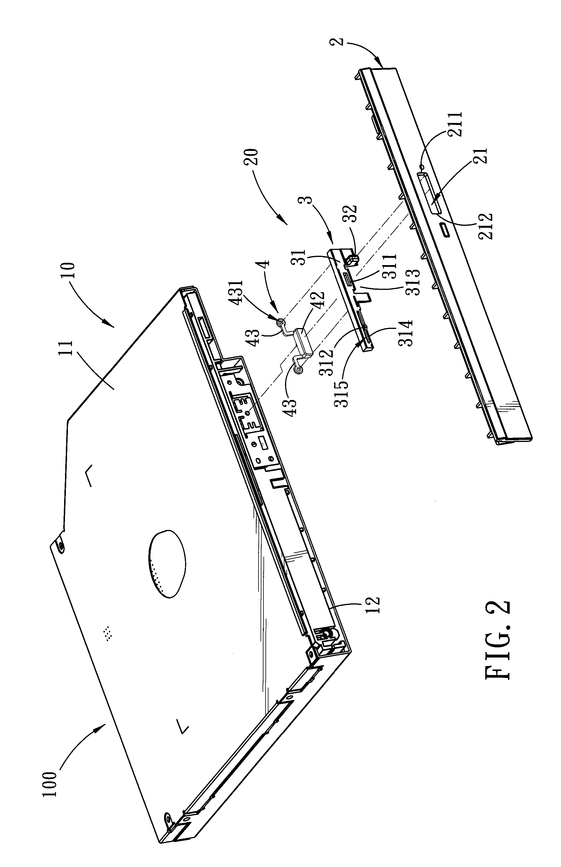
[0025]Referring to FIGS. 1 to 10, an optical disk drive 100 according to the embodiment of the present invention is adapted to be applied to a notebook computer or a desktop computer, and is shown to comprise a device body 10 and a locking mechanism 20.

[0026]The device body 10 includes an outer casing 11, and a tray 12 disposed in the outer casing 11 and adapted to hold an optical disk (not shown). An actuating element 13...


PUM

PropertyMeasurementUnit
assembly timeaaaaaaaaaa
resilientaaaaaaaaaa
timeaaaaaaaaaa

Abstract

A locking mechanism for installation on a device body, which includes an actuating element, includes a bezel having a through hole and a first positioning portion spaced apart from the through hole, and a locking element including a front operating portion extending through and movable along the through hole in a left-right direction, at least one guide pin extending in a front-rear direction, and an engaging portion. A press button is mounted slidably on the guide pin, and includes a contact portion adapted to be spaced apart from the actuating element in the left-right direction. The front operating portion is operable to move the press button between non-operative and operative positions, where the contact portion is adapted to be placed out of and in alignment with the actuating element, respectively. The engaging portion engages the first positioning portion when the press button is in the non-operative position.

Description

CROSS-REFERENCE TO RELATED APPLICATIONS[0001]This application claims priority of Taiwanese Patent Application No. 099137768 filed on Nov. 3, 2010, the disclosures of which is incorporated herein by reference.BACKGROUND OF THE INVENTION[0002]1. Field of the Invention[0003]This invention relates to a locking mechanism, and more particularly to a locking mechanism having a safety lock function and an optical disk drive having the same.[0004]2. Description of the Related Art[0005]An optical disk drive for a computer is usually operated by pressing a button to activate an ejection mechanism for ejecting out a tray. However, this kind of structure easily results in ejection of the tray due to accidental touching of the button by a user or through the presence of an external force, so that, during reading of optical disk data by the optical disk drive, the optical disk drive suddenly stops reading or become damaged when the tray is bumped.[0006]To overcome the aforesaid drawback, Taiwanese...

Claims


Application Information

Patent Timeline
Patent Type & Authority Patents(United States)
IPC IPC(8): G11B17/03
CPCG11B17/056Y10T292/0945Y10T292/1014Y10T292/097
Inventor LIU, KUO-CHUANYANG, CHE-SHENG
Owner WISTRON CORP
Why Eureka
Try Eureka