Insertion device for intraocular lens

a technology of insertion device and intraocular lens, which is applied in the field of intraocular lens insertion device, can solve the problems of increasing operation cost, user encountering difficulty in grasping charged quantity, and intraocular lens breakag

Active Publication Date: 2006-03-21
STAAR JAPAN
View PDF19 Cites 94 Cited by
  • Summary
  • Abstract
  • Description
  • Claims
  • Application Information

AI Technical Summary

Benefits of technology

[0016]A first object of the present invention is to provide an intraocular-lens insertion device which enables a user to inject a lubricant into an insertion tube and to grasp an injected quantity of ...

Problems solved by technology

However, since a mark for indicating an injected quantity is not provided, a user encounters difficulty in grasping the charged quantity.
Therefore, the user may inject the viscoelastic material in an excessive quantity, thereby increasing operation costs.
In addition, when the injected quantity is insufficient, a sufficient lubricating effect cannot be attained, resulting in occurrence of troubles such as breakage of an intraocular lens.
However, in the invention, since a hole for injecting the viscoelastic material is formed in the lens reception portion of the intermediate preparation region so as to be perpendicular to the center axis of the cannulae (insertion tube), a user encounters difficulty in controlling the direction of injection from the hole, resulting in failure to inject the viscoelastic material to the cannulae (insertion tube) side at which the viscoelastic material is needed for smooth passage of the lens or resulting in accidental injection of the viscoelastic material to the rear of the intermediate preparation region at which injection of the viscoelastic material is unnecessary, thereby increasing operation costs.
Although a technique for storing an intraocular lens in advance at the intermediate region located on the center axis of a push rod has been proposed, the intermediate region is difficult to form...

Method used


Image

  • Insertion device for intraocular lens
  • Insertion device for intraocular lens
  • Insertion device for intraocular lens

Examples


Embodiment Construction

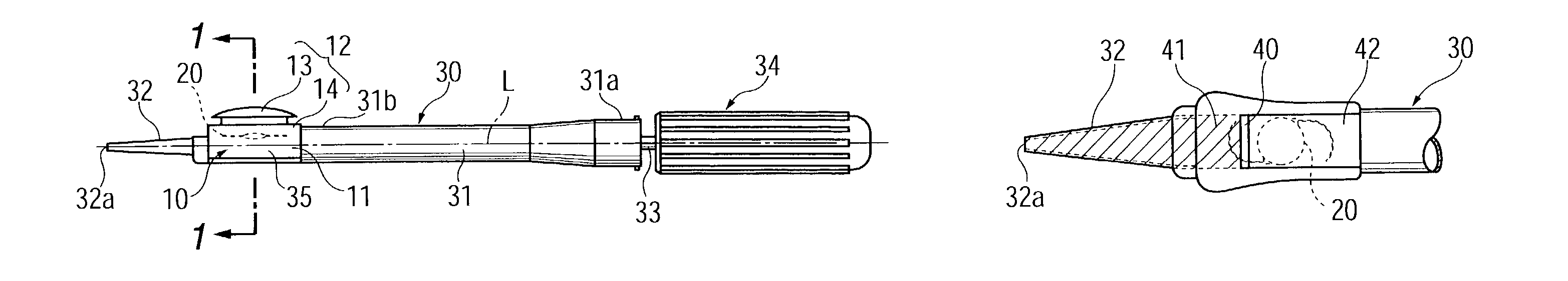
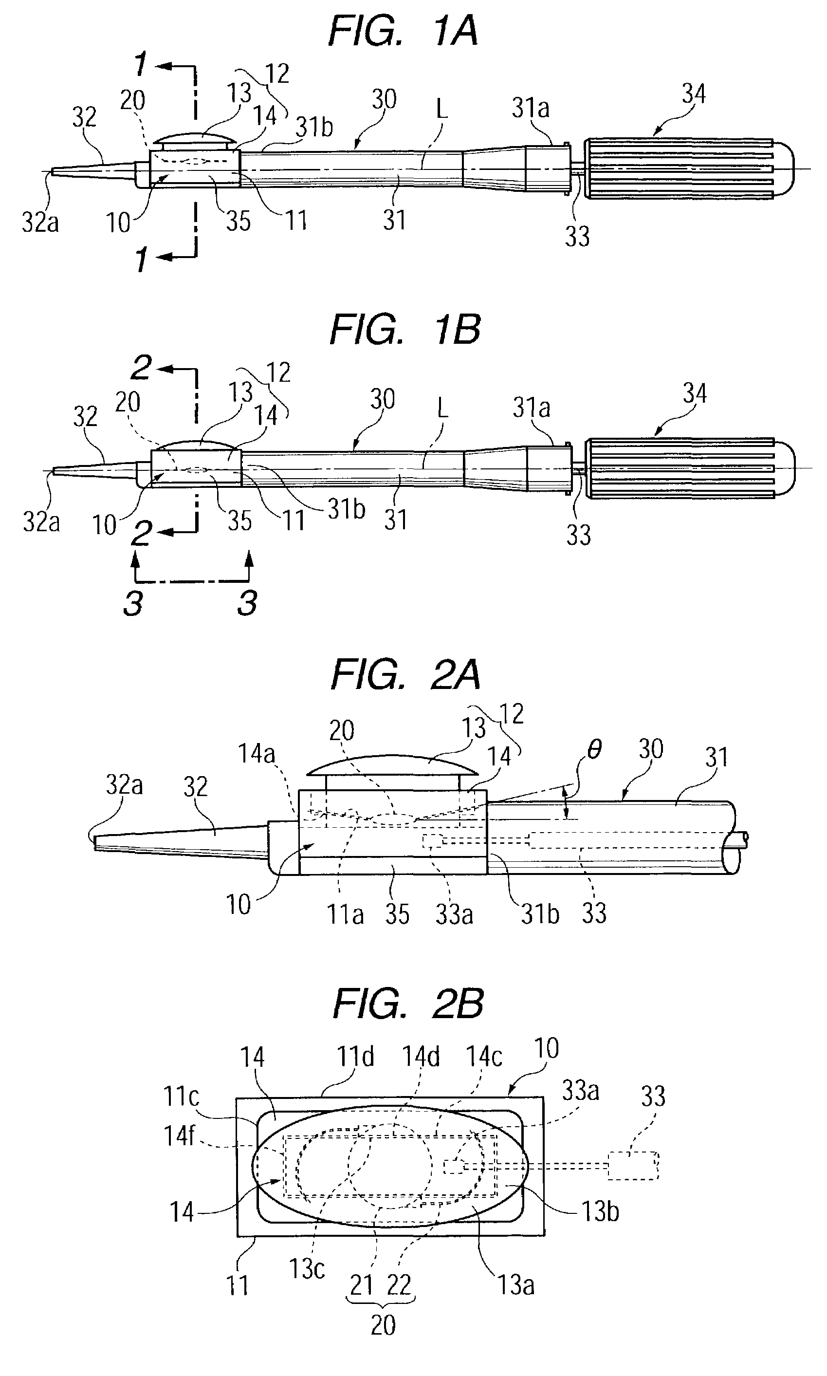
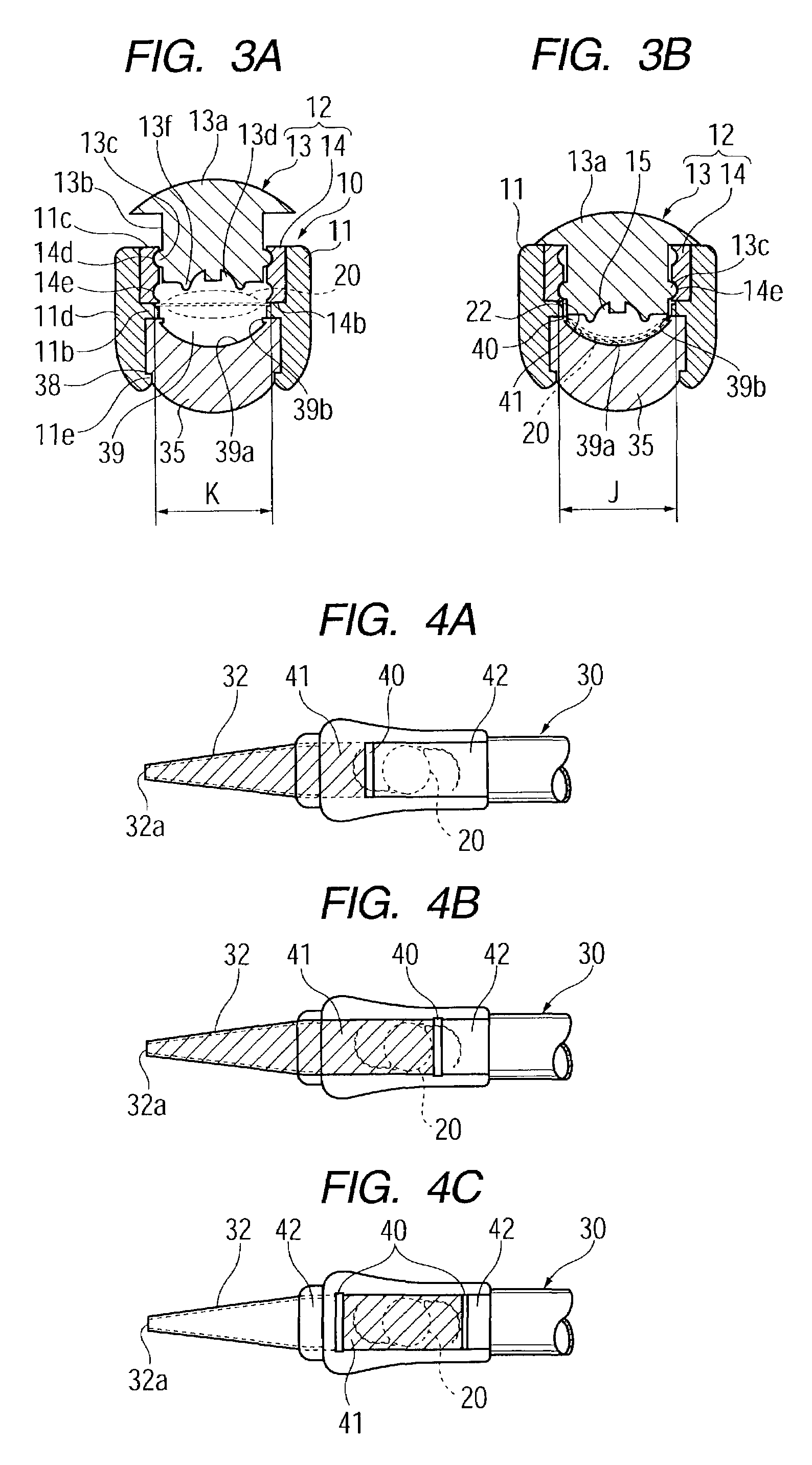
[0039]FIGS. 1A and 1B show one embodiment of an intraocular-lens insertion device according to the first aspect of the present invention. In the present embodiment, an intraocular lens 20 horizontally stored in a lens-holding member 10 can be moved between a first or standby position at which the vertical position of the center of the intraocular lens 20 does not coincide with the center axis of a push rod 33 of an insertion device 30, and a second or insertion position at which the vertical position of the center of the intraocular lens 20 coincides with the center axis of the push rod 33 of the insertion device 30, so that the intraocular lens 20 can be pushed out by the push rod 33. Further, a push member 13 is provided as a lens-moving mechanism for moving the intraocular lens 20 from the first or standby position to the second or insertion position.

[0040]FIG. 1A is a front view of the insertion device 30 to which the lens-holding member 10 has been attached and in which the int...


PUM


Abstract

An insertion device for an intraocular lens includes a lens-holding section having a cavity for accommodating an intraocular lens, a deforming section for deforming the lens to a reduced size, an insertion tube through which the deformed lens is inserted into an eye, a pusher mechanism for pushing and inserting the lens into the eye, and a lens-moving mechanism for moving the lens from a standby position to an insertion position at which the pusher mechanism can push and insert the lens into the eye. A lubricant is injected into the interior of the insertion tube and/or the cavity of the lens-holding section for smooth insertion of the lens. The insertion device has an indicating mark for indicating quantity of the injected lubricant. Further, the insertion device includes an erroneous operation prevention member for preventing accidental operation of the lens-moving mechanism.

Description

BACKGROUND OF THE INVENTION[0001]1. Field of the Invention[0002]The present invention relates to a device for inserting a deformable intraocular lens into the eye. Examples of such a deformable intraocular lens include a deformable intraocular lens that is inserted into the eye in place of the natural lens when the latter is physically extracted because of cataracts, and a vision correction lens that is inserted into the eye for the sole purpose of vision correction.[0003]2. Description of the Related Art[0004]In general, during cataract surgery, an intraocular lens is inserted into the eye, from which the natural lens has been removed (lens-removed eye), such that the intraocular lens is located in the original position previously occupied by the natural lens and restores vision. Various studies on the material and shape of such an intraocular lens have been carried out since Ridley performed the first implantation of an artificial lens in 1949.[0005]In recent years, in addition to...

Claims


Application Information

Patent Timeline
IPC IPC(8): A61F9/00A61F2/16
CPCA61F2/1675
Inventor KOBAYASHI, KENICHIOHNO, KENICHIROKIKUCHI, TOSHIKAZU
Owner STAAR JAPAN
Why Eureka
Try Eureka