Anvil for surgical stapler

a technology of surgical stapler and anvil, which is applied in the direction of surgical stapler, surgical forceps, paper/cardboard containers, etc., can solve problems such as protrusion formation, and achieve the effect of increasing the surface area

Inactive Publication Date: 2013-06-04
COVIDIEN LP
View PDF298 Cites 251 Cited by
  • Summary
  • Abstract
  • Description
  • Claims
  • Application Information

AI Technical Summary

Benefits of technology

[0018]In another aspect of the present disclosure, a surgical fastener applying apparatus is disclosed that includes a surgical fastener retention assembly accommodating a plurality of surgical fasteners each having first and second legs, and an anvil assembly including a tissue contacting surface with a plurality of fastener pockets formed therein. Each fastener pocket includes a pair of cavities that are each configured and dimensioned to receive a corresponding leg of one of the surgical fasteners. The cavities are connected by a linear section including a pair of arcuate forming surfaces that are each configured and dimensioned to engage and redirect a corresponding leg of the surgical fastener to achieve a formed configuration. The cavities may be substantially spherical in configuration, which provide increased surface area for contact with the legs of the surgical fastener and assist in guiding the legs of the surgical fasteners into contact with the arcuate forming surface.

Problems solved by technology

However, when the anvil head and the anvil plate are formed from different materials, welding may be inapplicable, while staking and swaging of the aforementioned rib may result in the formation of a protrusion that may in certain instances affect tissue clamped between the anvil head and the anvil plate.

Method used


Image

  • Anvil for surgical stapler
  • Anvil for surgical stapler
  • Anvil for surgical stapler

Examples


Embodiment Construction

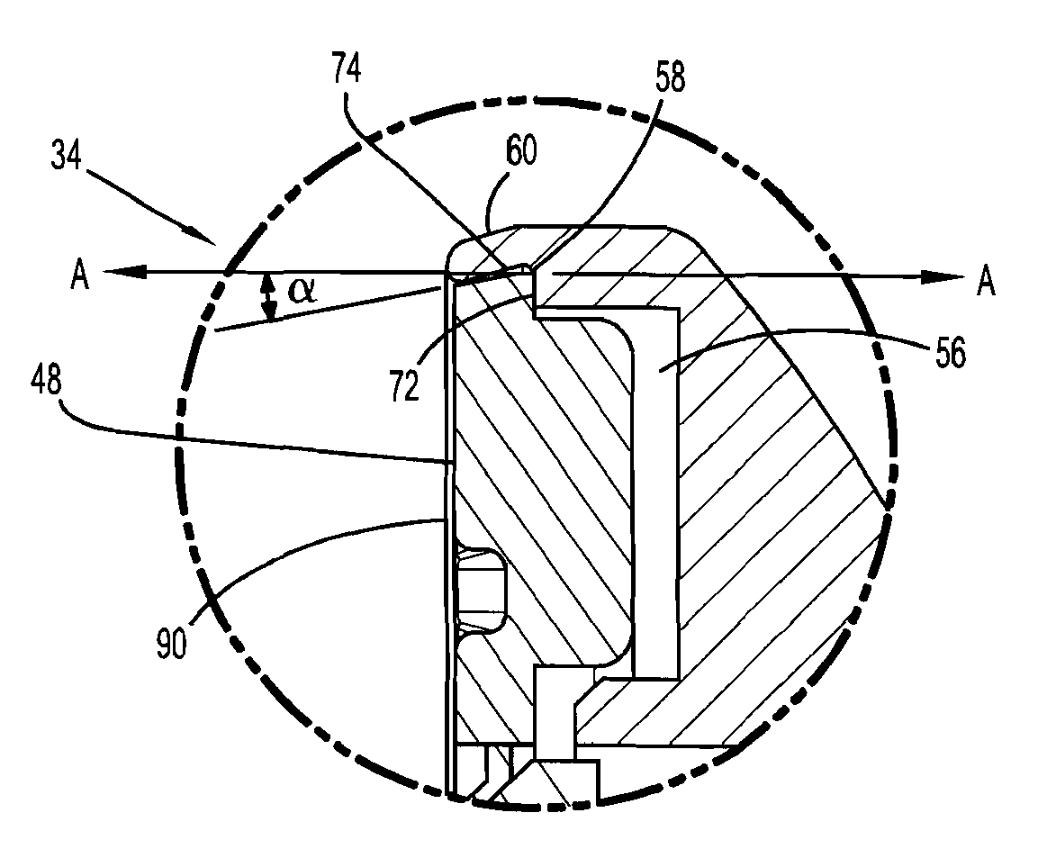
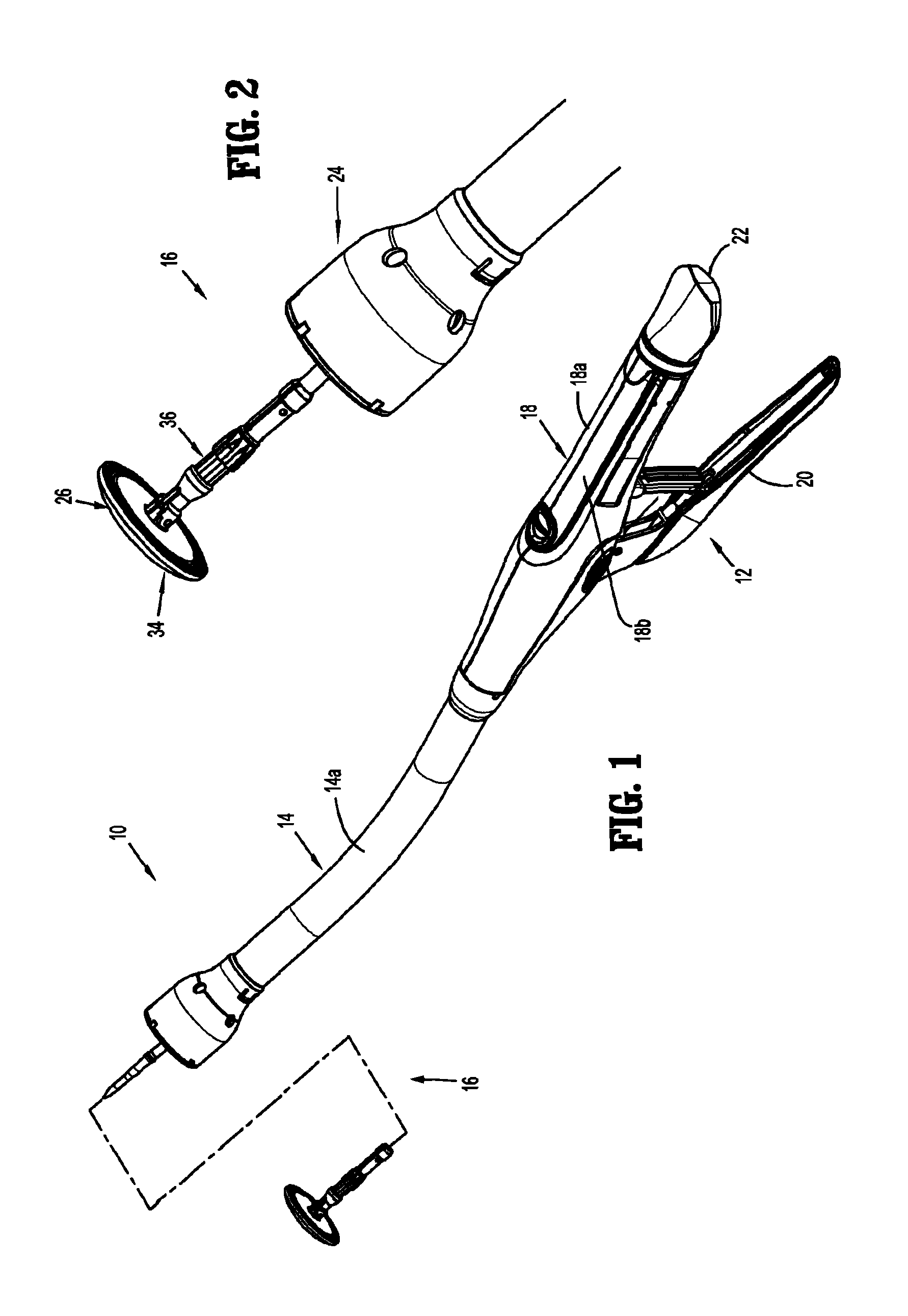
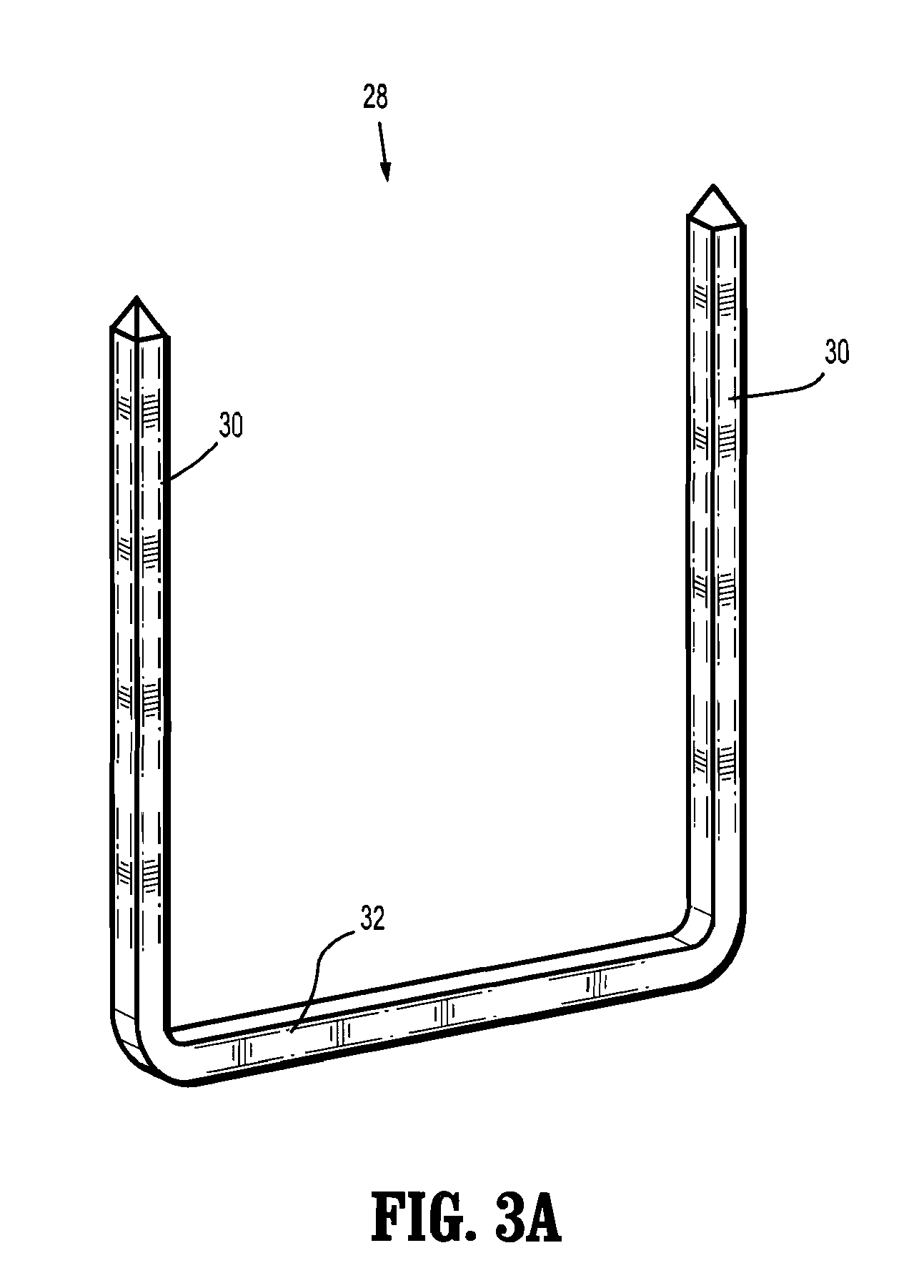
[0044]Various exemplary embodiments of the presently disclosed surgical fastener applying apparatus and anvil assembly for use therewith, as well as methods of manufacturing the same, will now be described in detail with reference to the drawings wherein like references numerals identify similar or identical elements. In the drawings and the following description, the term “proximal” will refer to the end of the surgical fastener applying apparatus, or component thereof, that is closer to the operator during proper use, while the term “distal” will refer to the end of the fastener cartridge that is further from the operator, as is traditional and conventional in the art. In addition, the term “surgical fastener” should be understood to include any substantially rigid structure formed of a biocompatible material that is suitable for the intended purpose of joining tissue together, including but not being limited to surgical staples, clips, and the like.

[0045]FIG. 1 illustrates a surg...


PUM

PropertyMeasurementUnit
acute angleaaaaaaaaaa
angleaaaaaaaaaa

Abstract

An anvil assembly for use therewith a surgical fastener applying apparatus including an anvil plate and an anvil head configured and dimensioned to support the anvil plate. The anvil plate and the anvil head may be formed from different materials. The anvil plate can include a tapered outer side wall allowing the anvil assembly to realize a substantially uniform proximal-most surface upon assembly.

Description

[0001]This application claims priority from provisional application 61 / 150,429 filed Feb. 6, 2009, the entire contents of which are incorporated herein by reference.BACKGROUND[0002]1. Technical Field[0003]The present disclosure relates to surgical fastener applying apparatus, and more particularly, to an anvil assembly for use therewith, as well as methods of manufacturing the same.[0004]2. Background of the Related Art[0005]Many varieties of surgical fastener applying apparatus are known in the art, some of which are specifically adapted for use in various surgical procedures such as end-to-end anastomosis, circular end-to-end anastomosis, open gastrointestinal anastomosis, endoscopic gastrointestinal anastomosis, and transverse anastomosis. Suitable examples of fastener applying apparatus that may be used during the course of such procedures can be seen in U.S. Pat. Nos. 5,915,616; 6,202,914; 5,865,361; and 5,964,394.[0006]Surgical fastener applying apparatus for use in performing...

Claims


Application Information

Patent Timeline
Patent Type & Authority Patents(United States)
IPC IPC(8): A61B17/068
CPCA61B17/115A61B17/068A61B17/072A61B17/07207A61B17/1155A61B2017/00526A61B2017/00831Y10T29/49908A61B2017/07214A61B2017/07257A61B2017/07264A61B2017/2927A61B2017/00853A61B17/0644
Inventor MILLIMAN, KEITH L.
Owner COVIDIEN LP
Why Eureka
Try Eureka