Heating cartridge for thermostatic element and method for manufacturing same, as well as thermostatic valve comprising such a cartridge

a technology of thermostatic elements and heating cartridges, which is applied in the direction of heating element materials, heating arrangements, heating elements, etc., can solve the problems of crippling molding costs, difficult to achieve radical solutions in practice, and inability to meet the different geometries of heating cartridges

Inactive Publication Date: 2013-06-04
VERNET SA
View PDF3 Cites 2 Cited by
  • Summary
  • Abstract
  • Description
  • Claims
  • Application Information

AI Technical Summary

Benefits of technology

[0008]The aim of the present invention is to propose a heating cartridge whereof the connection between its tube and its base is both resistant and precisely adaptable to various geometries of heating cartridges, all while being economical to carry out.
[0013]The basic idea of the invention is not to try to realize the base by coating the entire terminal portion of the tube with plastic, which makes the base massive and not very precise, but to overmold the inside of the free end of the tube, flared specifically. To do this, said flared end presents an overmold face, turned opposite the rest of the tube, including components which are both radial and axial in relation to the axis of the tube: the radial component of the overmold interface between the tube and the base allows good transmission of axial strains, which avoids, during use, the tube damaging the base, in particular by shearing it, while the axial component of this interface makes it possible, on one hand, to improve the transverse positioning of the base, in particular by facilitating the placement of injection molds of the plastic substance of the base, and, on the other hand, to absorb transverse strains.
[0014]It is then advantageously possible to overmold the base by only making it extend axially from a single axial side of the terminal portion of the tube including the flared end. The flared end of the tube can thus serve as a reliable and precise reference to impose the axial dimension of the base during its molding, with a corresponding injection mold adjustment. In other words, it is the molding tool which gives the heating cartridge its effective functional length, by precisely controlling the measurement between the end of the heating cartridge and the axial face opposite the base, which avoids providing attached adjustment means, such as adjustment systems through screws, added wedges, etc.
[0015]Advantageously, a heating cartridge according to the invention also includes a gasket, preferably only one, which simultaneously surrounds the flared free end of the tube and is inserted between this flared free end and the base. This gasket which, in particular, is a shape gasket, makes it possible to simultaneously seal the inside of the tube and the electric connection supported by the base. Moreover, the closing of the injection mold of the base can be done on the gasket, which makes it possible to accommodate the dispersions of the total axial length of the heating cartridge.

Problems solved by technology

This radical solution has proven difficult to carry out in practice, inasmuch as it requires having injection molds adapted, simultaneously, to each possible shape and size for the tube and the total axial dimension that one wishes to obtain for the heating cartridge.
The molding cost to meet the different geometries of heating cartridges therefore becomes crippling.

Method used


Image

  • Heating cartridge for thermostatic element and method for manufacturing same, as well as thermostatic valve comprising such a cartridge
  • Heating cartridge for thermostatic element and method for manufacturing same, as well as thermostatic valve comprising such a cartridge
  • Heating cartridge for thermostatic element and method for manufacturing same, as well as thermostatic valve comprising such a cartridge

Examples


Embodiment Construction

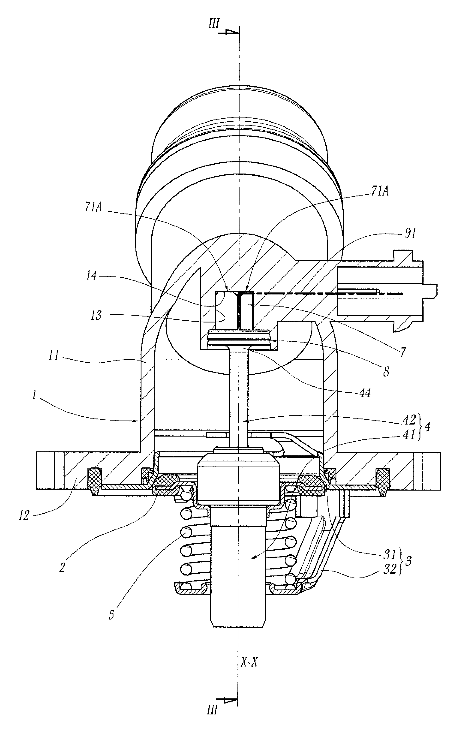
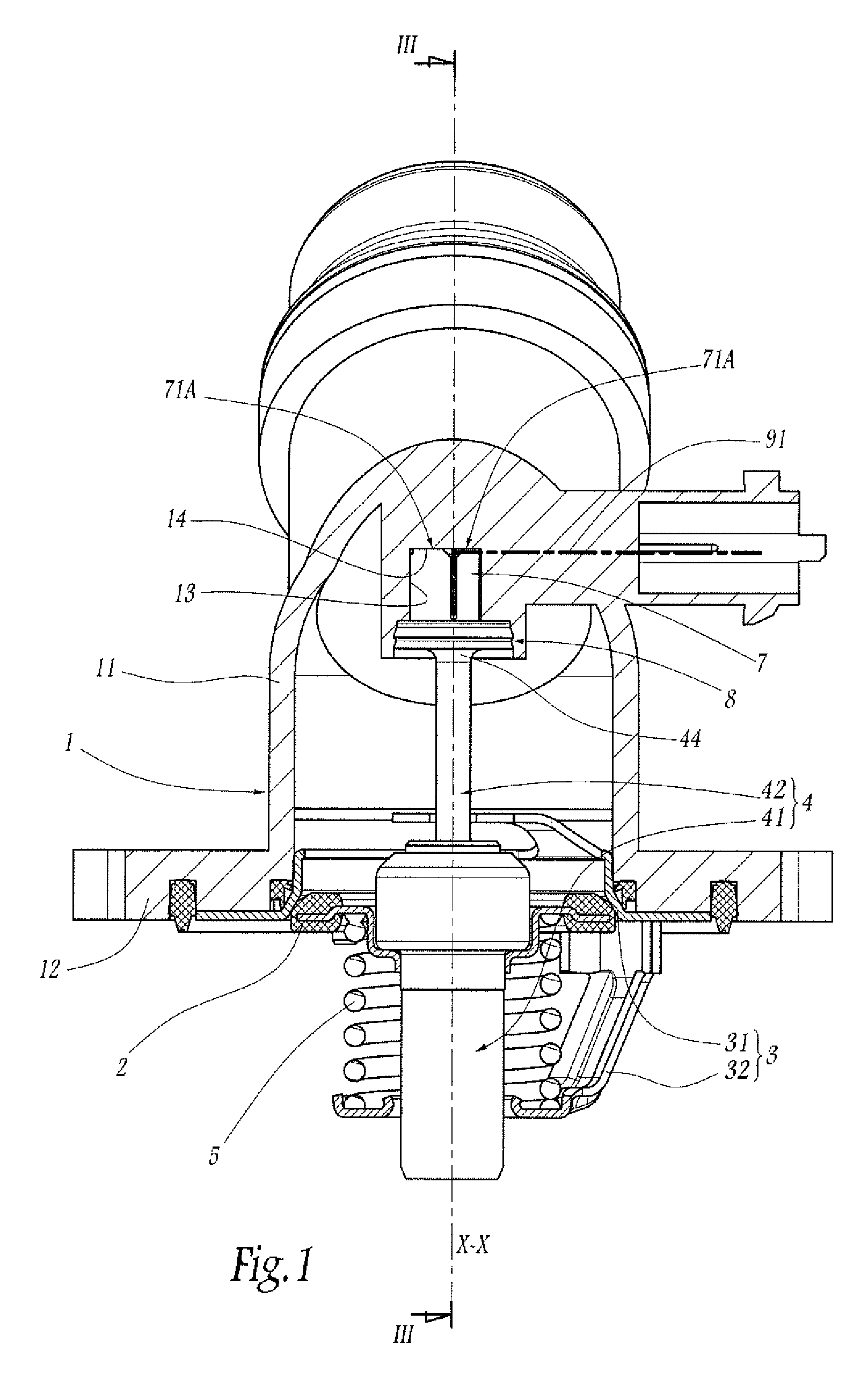
[0035]FIG. 1 illustrates a thermostatic valve including a case 1 in which is designed to circulate, regulated by the other components of the valve, a fluid, in particular a coolant liquid when the valve belongs to a cooling circuit for a thermal engine. The case 1 comprises a tubular main body 11, here with a bent global shape, one portion of which extends in length centered around an axis X-X belonging to the cutting plane of FIG. 1. During use, the aforementioned fluid flows through the body 11, between its two longitudinal ends, while being regulated, here at the end of the portion of the body 11 centered on the axis X-X, by an isolating plug 2 centered on the axis X-X and which can be moved in translation along that axis: when said plug is pushed sealably against a seat 31 defined by a rigid armature 3 connected fixedly to a clamping plate 12 of the case 1, as illustrated in FIG. 1, the flow of the fluid is interrupted, whereas, when the isolating plug 2 is separated from the se...


PUM

PropertyMeasurementUnit
thermally conductiveaaaaaaaaaa
temperatureaaaaaaaaaa
currentaaaaaaaaaa

Abstract

This heating cartridge includes a thermally conductive tube (42) to be immersed in a thermo-expandable substance of the thermostatic element, electric heating means (6) arranged inside the tube, and a base (7) made of a plastic substance, integral with a terminal longitudinal portion (44) of the tube and adapted to support the electric connection between the heating means and an external current source. In order to make the connection between the base and the tube both resistant and precisely adaptable to various heating cartridge geometries, and to do so economically, the terminal portion of the tube comprises an outwardly flared free end (45), which extends protruding both radially and axially from the rest of the terminal portion and in which the base is attached by overmolding.

Description

BACKGROUND OF THE INVENTION[0001]1. Field of the Invention[0002]The present invention relates to a heating cartridge for a thermostatic element, as well as a method for manufacturing such a cartridge. It also relates to a thermostatic valve including such a cartridge.[0003]2. Brief Description of the Related Art[0004]In many applications of the fluidics field, in particular for cooling of thermal engines of vehicles, thermostatic valves are used to distribute a fluid entering into different circulation channels, depending on the temperature of that fluid. These valves are called thermostatic in the sense that the movement of their internal plug(s) is controlled by a thermostatic element, i.e. an element which comprises a cup containing a thermo-expandable substance and a piston which is slidingly displaceable with respect to the cup under the action of the thermo-expandable substance during the expansion thereof.[0005]In order to distribute the fluid depending on other parameters, i...

Claims


Application Information

Patent Timeline
Patent Type & Authority Patents(United States)
IPC IPC(8): G05D23/02G05D23/08H05B3/10H05B3/08
CPCG05D23/022H05B3/80H05B3/06Y10T29/49083
Inventor POTTIE, NICOLASMARAUX, THIERRY
Owner VERNET SA
Why Eureka
Try Eureka