Method and system for mapping the shape of a head under operating conditions

a mapping system and head technology, applied in the direction of maintaining the head carrier alignment, functional testing of recording heads, instruments, etc., can solve the problems of limited spatial resolution, limited utility of information provided, and significant amount of interpretation

Inactive Publication Date: 2013-06-04
WESTERN DIGITAL TECH INC
View PDF15 Cites 48 Cited by
  • Summary
  • Abstract
  • Description
  • Claims
  • Application Information

AI Technical Summary

Problems solved by technology

Although the conventional method 50 functions, the information provided may have limited utility.
Inferring the protrusion from thermal data may require a significant amount of interpretation and have limited spatial resolution.
Profilometry may require equal wear to be assumed and may not be capable of providing a deformation profile under normal operating conditions.
Without an accurate determination of the profile of the ABS 22, optimization of the distance between the slider 20 and disk 12 may be difficult.

Method used


Image

  • Method and system for mapping the shape of a head under operating conditions
  • Method and system for mapping the shape of a head under operating conditions
  • Method and system for mapping the shape of a head under operating conditions

Examples


Embodiment Construction

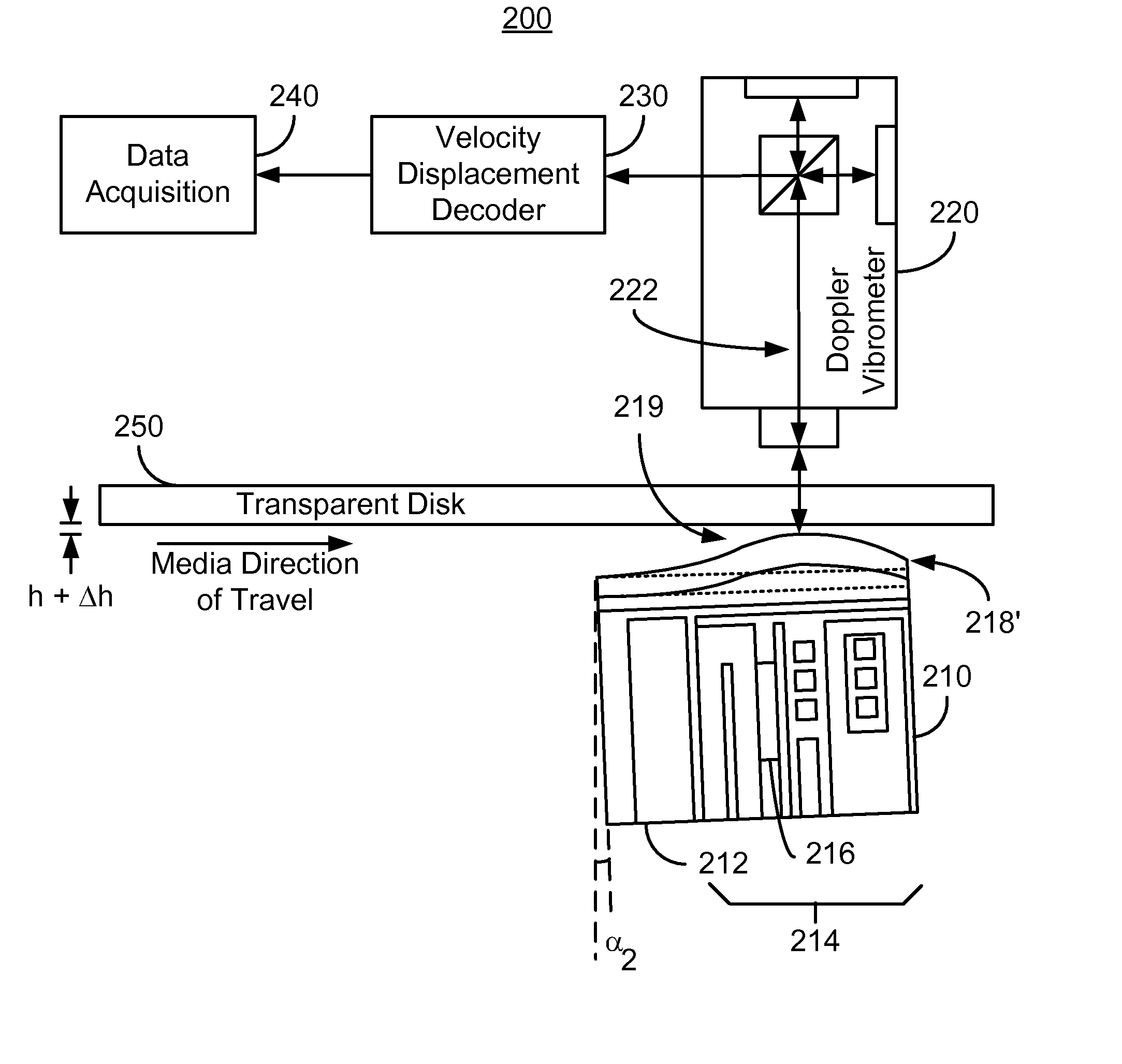
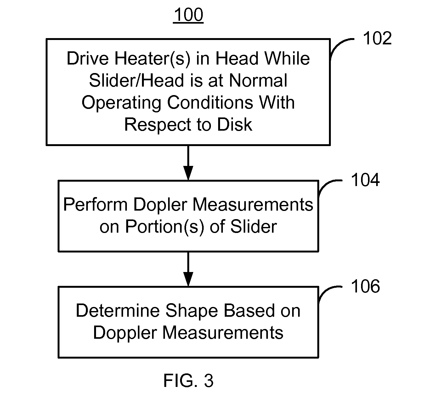
[0014]FIG. 3 is a flow chart depicting an exemplary embodiment of a method 100 for determining the profile of a surface a disk drive. Although certain steps are shown, some steps may be omitted, interleaved, performed in another order, and / or combined. The method 100 is used in determining a shape of a portion of an air-bearing surface (ABS) of a head residing on a slider. The ABS is configured to fly at a fly height from and with a velocity with respect to a disk during normal operating conditions. Stated differently, the disk drive is designed such that the ABS of the head / slider flies at the fly height when the disk is spun at an angular velocity. This angular velocity translates to a linear velocity at particular portions of the disk. The actual fly height and velocity corresponding to the normal operating conditions may vary depending upon the specifics of the design of the disk drive.

[0015]One or more heaters residing in the slider are driven while the slider is at substantial...


PUM

PropertyMeasurementUnit
velocityaaaaaaaaaa
transparentaaaaaaaaaa
shapeaaaaaaaaaa

Abstract

A method and system for determining a shape of a portion of an air-bearing surface (ABS) of a head residing on a slider are described. The ABS is configured to fly at a fly height from and with a velocity with respect to a disk during normal operating conditions. The method and system include driving at least one heater residing in the head while the slider is substantially at the normal operating conditions with respect to the disk and the fly height. The shape of the portion of the ABS changes in response to the heater(s) being driven. The method and system also include performing Doppler measurements on the slider while the heater is driven. The shape may then be determined based on the Doppler measurements.

Description

CROSS REFERENCE TO RELATED APPLICATIONS[0001]The present application claims priority from provisional application Ser. No. 61 / 347,775, filed May 24, 2010, entitled “Measuring and Spatial Mapping Thermal Deformation”, assigned to the assignee of the present application.BACKGROUND[0002]FIG. 1 depicts a side view of portion of a conventional magnetic recording disk drive 10. FIG. 1 is not to scale and only portions of the conventional disk drive 10 are shown. The conventional disk drive 10 includes a disk 12 and a conventional slider 20 that is typically attached to a suspension (not shown). In operation, the slider 20 flies a distance, known as the fly height h, above the conventional disk 12 while the conventional disk 12 spins. Thus, the slider 20 and disk 12 are in relative motion. An air bearing is formed between the conventional disk 12 and the slider 20 at the air-bearing surface (ABS) 22 due to this relative motion. Using magnetic recording write and read transducers on the sli...

Claims


Application Information

Patent Timeline
Patent Type & Authority Patents(United States)
IPC IPC(8): G01B11/02G11B5/596G11B5/00
CPCG11B5/607G11B5/455
Inventor PRABHAKARAN, VIJAYGAN, WUXINGPUST, LADISLAV R.FOWLER, DAVID E.ZHENG, LANSHI
Owner WESTERN DIGITAL TECH INC
Why Eureka
Try Eureka