System and method for determining head-disk contact in a magnetic recording disk drive

a magnetic recording disk and head-disk technology, applied in the field of magnetic recording disk drives, can solve problems such as data loss, disk drive complete failure, and head “crash” during operation

Inactive Publication Date: 2007-05-08
WESTERN DIGITAL TECH INC
View PDF40 Cites 53 Cited by
  • Summary
  • Abstract
  • Description
  • Claims
  • Application Information

AI Technical Summary

Benefits of technology

[0010]The invention is system and method for determining HDC in a disk drive using the signal from the magnetoresistive (MR) read head. The signal is measured over a low-frequency range, with the slider out-of-contact with the disk, to develop a reference value. The signal is then measured over the same low-frequency range and this measured value is compared to the reference value. In one aspect of the system and method, the analog MR signal is digitized and input to a digital signal processor with circuitry and/or software for integra

Problems solved by technology

Disk drives are susceptible to failure of the slider-disk interface which can result in a head

Method used


Image

  • System and method for determining head-disk contact in a magnetic recording disk drive
  • System and method for determining head-disk contact in a magnetic recording disk drive
  • System and method for determining head-disk contact in a magnetic recording disk drive

Examples


Embodiment Construction

[0019]The invention is applicable not only to magnetic recording disk drives, but also to head-disk testers or “spin stands” that are used in disk drive manufacturing to design and test the head-disk interface in magnetic recording disk drives. The invention is applicable to conventional disk drives that do not have active control of the head-disk spacing, as well as to disk drives with head fly-height actuators that move the read-write head relative to the slider or alter the air-flow or shape of the slider's air-bearing surface (ABS) to control the head-disk spacing.

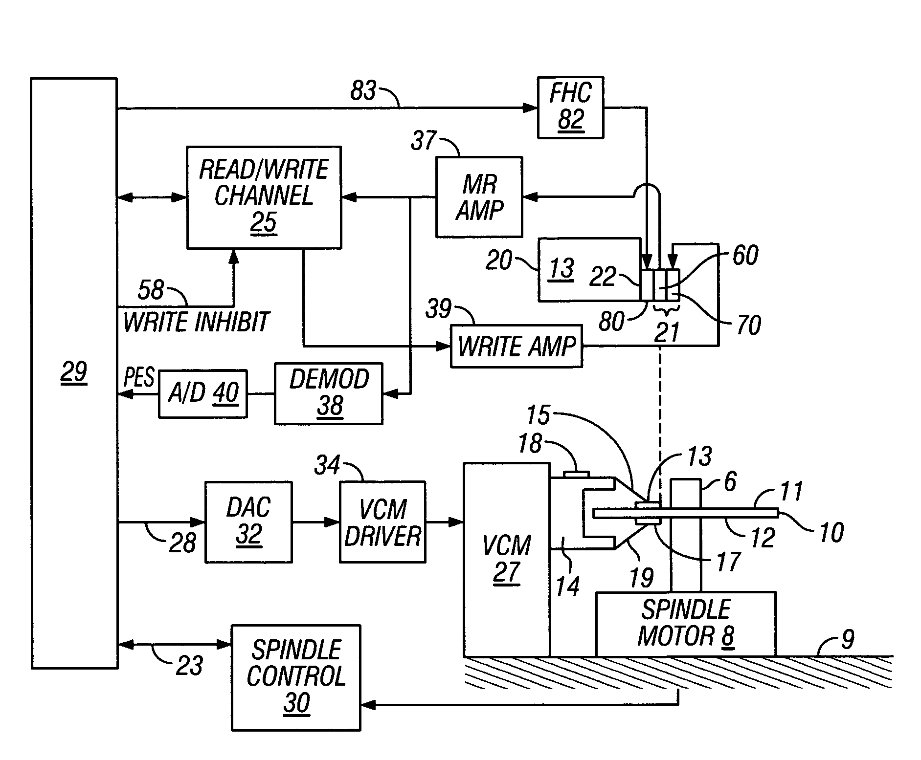
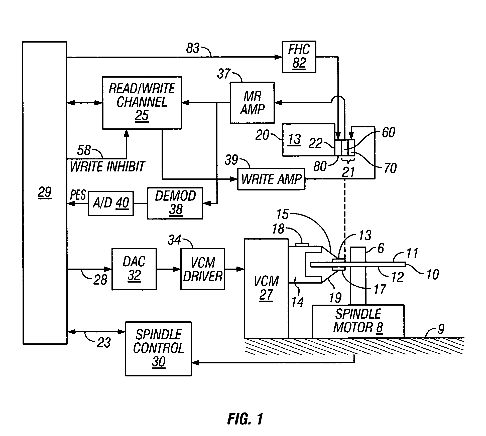
[0020]FIG. 1 is a schematic block diagram of a magnetic recording disk drive. The disk drive includes a magnetic recording disk 10 with surfaces 11 and 12, each of which contains a magnetic recording layer. The disk 10 is mounted on a spindle 6 and rotated by a spindle motor 8 about an axis perpendicular to the disk surfaces 11, 12. A head carrier or slider 13 is positioned near the surface 11 of disk 10. Slider 13 is ...


PUM


Abstract

A system and method for determining head-disk contact (HDC) in a magnetic recording disk drive uses the signal from the magnetoresistive (MR) read head. The analog MR signal is digitized and input to a digital signal processor with circuitry and/or software for integrating the signal amplitude over a low-frequency range. The calculated value from the integration when the slider is out-of-contact with the disk is a reference value. The same integration is then performed during operation of the disk drive and the measured value is compared to the reference value. If the measured value exceeds the reference value by some predetermined amount, this is an indication of the onset of HDC or that HDC has occurred. The method can be used in head-disk testers to facilitate the design and testing of disk drive components, such as slider-suspension assemblies and fly-height actuators located on the slider to alter the head-disk spacing, and in disk drives to control fly-height actuators and to take corrective action prior to HDC.

Description

RELATED APPLICATION[0001]Concurrently-filed application Ser. No. 11 / 320,425 relates to a SYSTEM AND METHOD FOR CALIBRATING AND CONTROLLING A FLY-HEIGHT ACTUATOR IN A MAGNETIC RECORDING DISK DRIVE.BACKGROUND OF THE INVENTION[0002]1. Field of the Invention[0003]This invention relates to magnetic recording disk drives, and more particularly to a system and method for determining contact of the read / write head or the head carrier with the disk.[0004]2. Description of the Related Art[0005]Magnetic recording hard disk drives use a read / write transducer or head mounted on a head carrier for reading and / or writing data to the disk. The head carrier is typically an air-bearing slider attached to an actuator arm by a suspension and positioned very close to the disk surface by the suspension. There are typically a stack of disks in the disk drive with a slider-suspension assembly associated with each disk surface in the stack.[0006]The separation between the head and the disk surface is called...

Claims


Application Information

Patent Timeline
IPC IPC(8): G11B27/36G11B21/02G11B5/02
CPCG11B5/455G11B5/6005G11B5/6064G11B19/04G11B27/36G11B2220/2516
Inventor CHE, XIAODONGHUANG, WEIDONGLAM, TERENCE TIN-LOKLIN, ZHONG-HENGSHTEYN, ALEX
Owner WESTERN DIGITAL TECH INC
Why Eureka
Try Eureka