Battery tester with battery replacement output

a battery tester and battery replacement technology, applied in the field of storage batteries, can solve the problems of increased cost and potential damage to the battery and vehicle, inconvenient use of service personnel, and insufficient information provided by the battery tester regarding the condition of the battery,

Inactive Publication Date: 2005-06-14
MIDTRONICS
View PDF301 Cites 106 Cited by
  • Summary
  • Abstract
  • Description
  • Claims
  • Application Information

AI Technical Summary

Problems solved by technology

However, in certain testing situations, a battery tester providing information limited to the condition of the battery may be inadequate.
Since current testers typically do not provide such information, service personnel usually have to suggest suitable battery replacement options to the customer.
Reliance on the recommendations of the service personnel regarding battery replacement may not be advantageous for the testing facility as well as the customer.
In general, inadequate and inaccurate battery replacement information can lead to the selection of a battery that is unsuitable for the conditions under which the vehicle is operated, which may result in additional cost and potential damage to the battery and vehicle.

Method used


Image

  • Battery tester with battery replacement output
  • Battery tester with battery replacement output
  • Battery tester with battery replacement output

Examples


Embodiment Construction

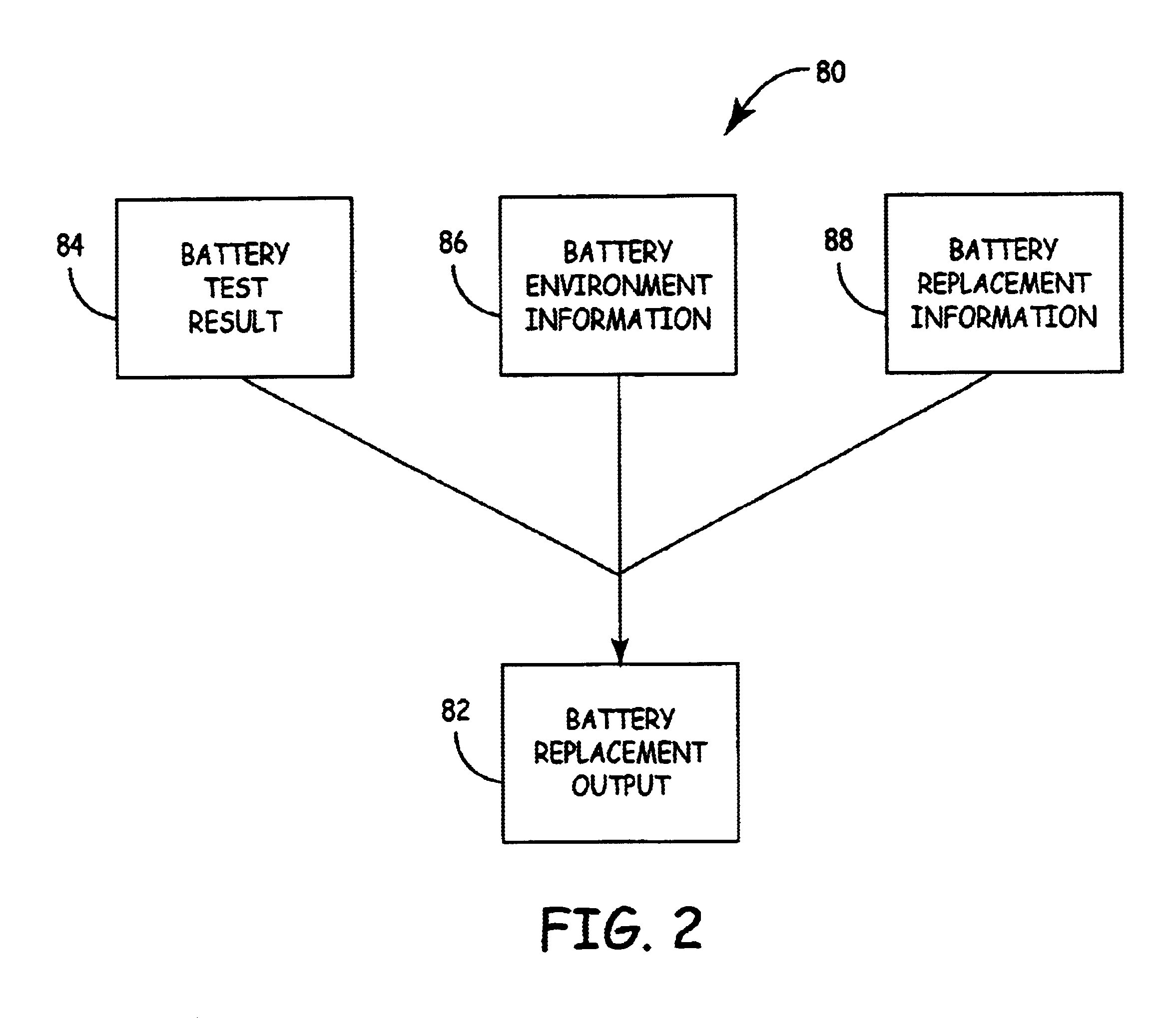
[0009]The present invention provides an apparatus and method for conducting a battery test and utilizing a test result, battery replacement information and battery environment information to provide an output related to a replacement battery or battery replacement options.

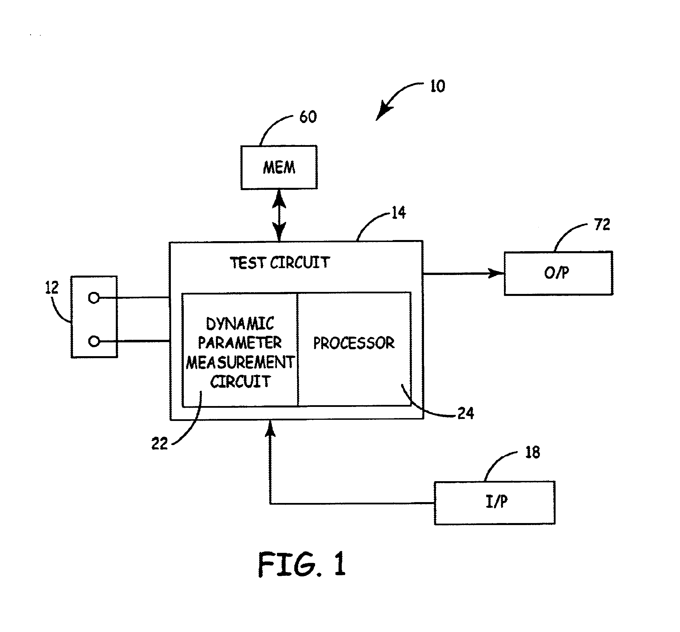
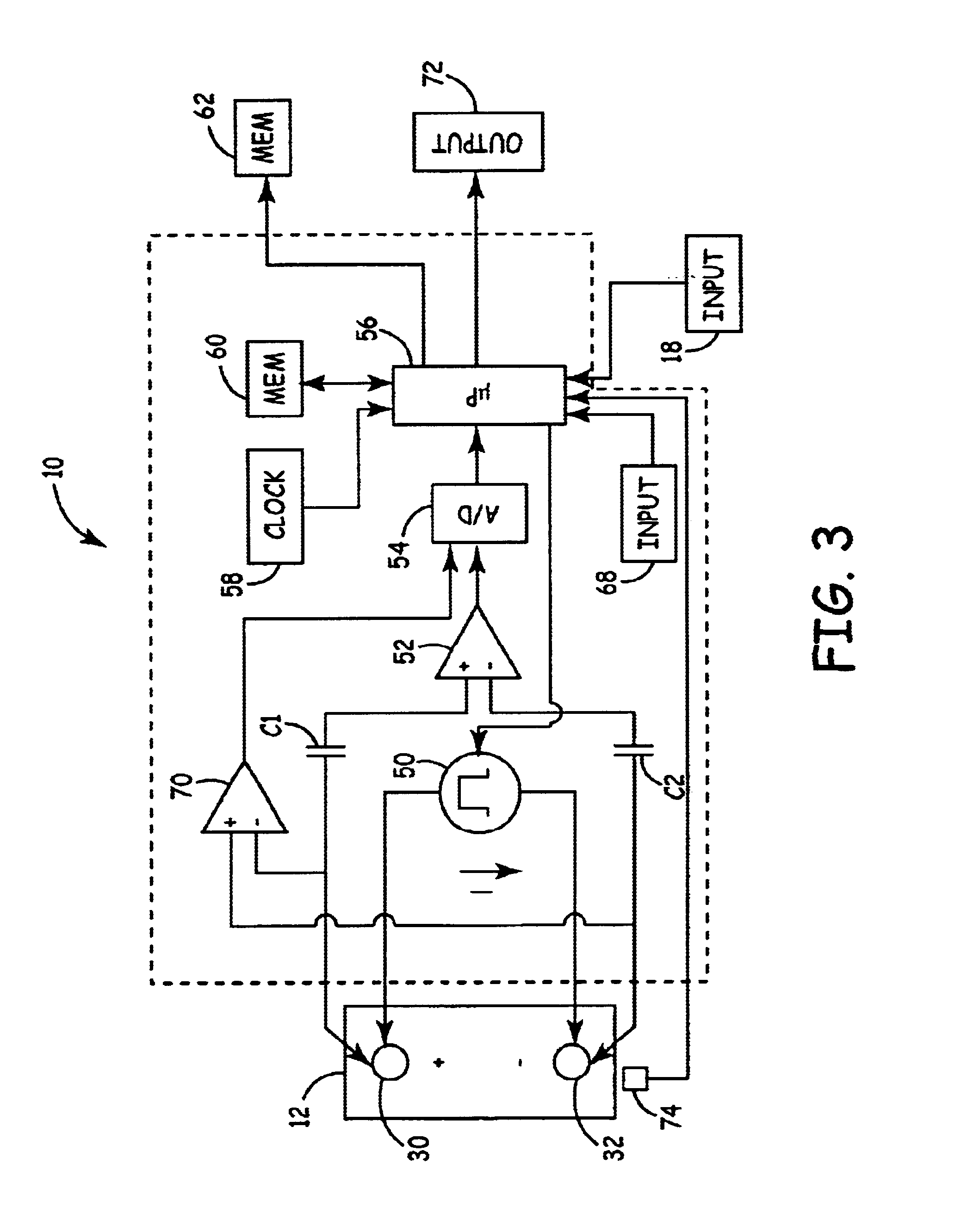
[0010]FIG. 1 is a very simplified block diagram of a battery tester 10 in accordance with an illustrative embodiment of the present invention. Note that FIG. 1 is a simplified diagram of a specific type of battery tester. However, the present invention is applicable to any type of battery tester including those which do not use dynamic parameters. Other types of example testers include testers that conduct load tests, current based tests, voltage based tests, tests which apply various conditions or observe various performance parameters of a battery, etc. Battery tester 10 includes a test circuit 14 that directly couples to vehicle battery 12. Test circuit 14 includes dynamic parameter measurement circuit 22 and pr...


PUM

PropertyMeasurementUnit
sizeaaaaaaaaaa
conductanceaaaaaaaaaa
temperatureaaaaaaaaaa

Abstract

An electronic battery tester for testing a storage battery. The battery tester provides a replacement battery output as a function of battery environment information and battery replacement information.

Description

BACKGROUND OF THE INVENTION[0001]The present invention relates to storage batteries. More specifically, the present invention relates to a battery system tester for testing storage batteries.[0002]Many attempts have been made to test storage batteries. One technique which has been pioneered by Dr. Keith S. Champlin and Midtronics, Inc. of Burr Ridge, Ill. relates to measuring the conductance of batteries to determine their condition. This technique is described in a number of United States patents, for example, U.S. Pat. No. 3,873,911, issued Mar. 25, 1975, to Champlin, entitled ELECTRONIC BATTERY TESTING DEVICE; U.S. Pat. No. 3,909,708, issued Sep. 30, 1975, to Champlin, entitled ELECTRONIC BATTERY TESTING DEVICE; U.S. Pat. No. 4,816,768, issued Mar. 28, 1989, to Champlin, entitled ELECTRONIC BATTERY TESTING DEVICE; U.S. Pat. No. 4,825,170, issued Apr. 25, 1989, to Champlin, entitled ELECTRONIC BATTERY TESTING DEVICE WITH AUTOMATIC VOLTAGE SCALING; U.S. Pat. No. 4,881,038, issued N...

Claims


Application Information

Patent Timeline
Patent Type & Authority Patents(United States)
IPC IPC(8): G01R31/36
CPCG01R31/3648G01R31/3675G01R31/3665G01R31/374G01R31/378
Inventor BERTNESS, KEVIN I.SAMPSON, WILLIAM G.
Owner MIDTRONICS
Why Eureka
Try Eureka