

Battery testers with secondary functionality
a technology of battery testers and functionalities, applied in the field of battery testers, can solve the problem of limited range of battery testers
- Summary
- Abstract
- Description
- Claims
- Application Information
AI Technical Summary
Problems solved by technology
Method used
Image

Examples
Embodiment Construction
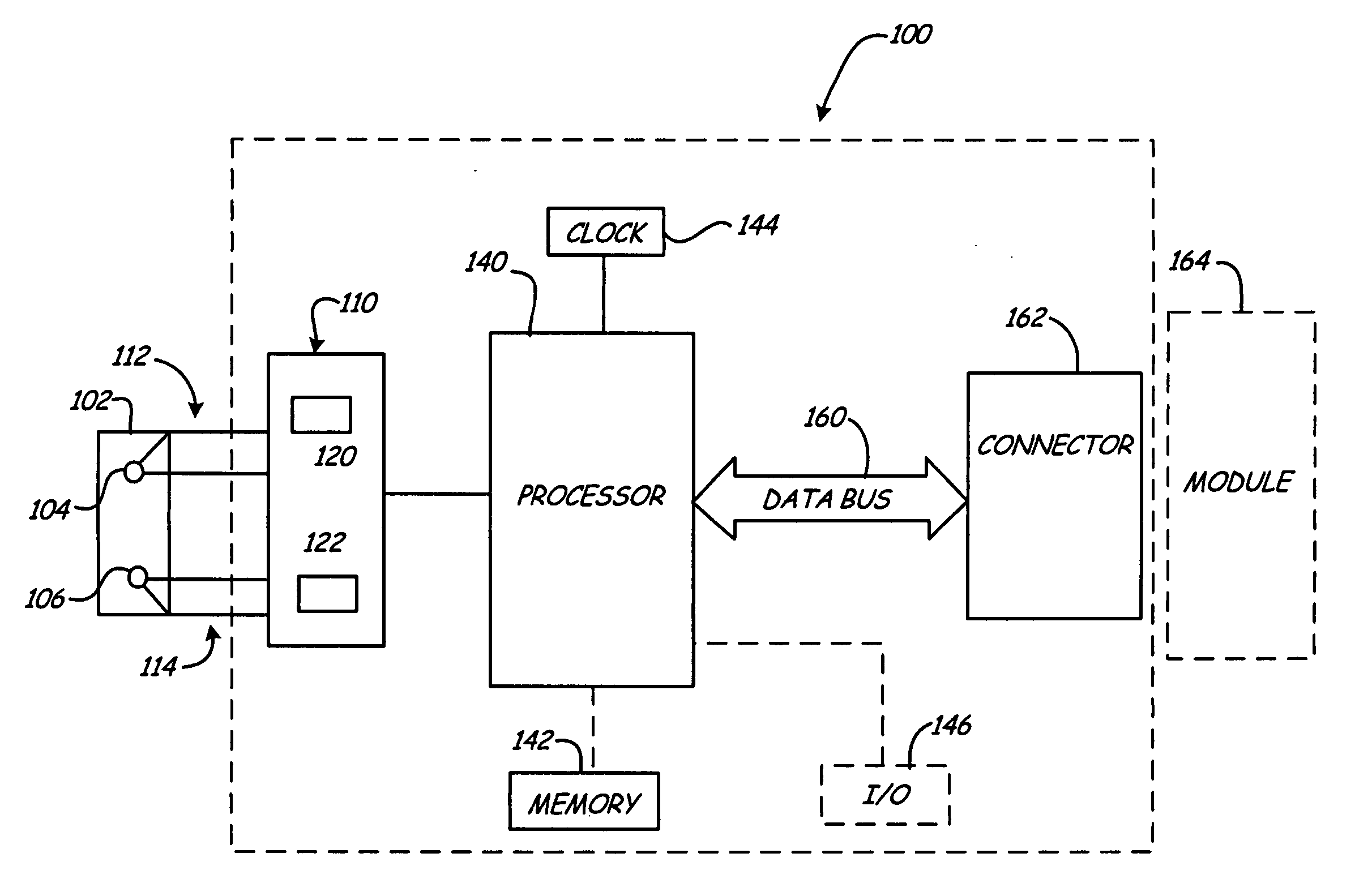
[0011] The present invention provides an electronic battery tester for testing storage batteries in which removable modules can be selectively coupled to the electronic battery tester to extend the functionality of the device. In one configuration, the additional functionality is built into the device and is not carried in a removable module. In various aspects, the invention includes an electronic battery tester adapted to couple to a removable module, a removable module itself and a combination of an electronic battery tester and a removable module. The following is a more detailed description of the invention. However, in broad aspects, the present invention is not limited to the specific configurations or example modules set forth herein.
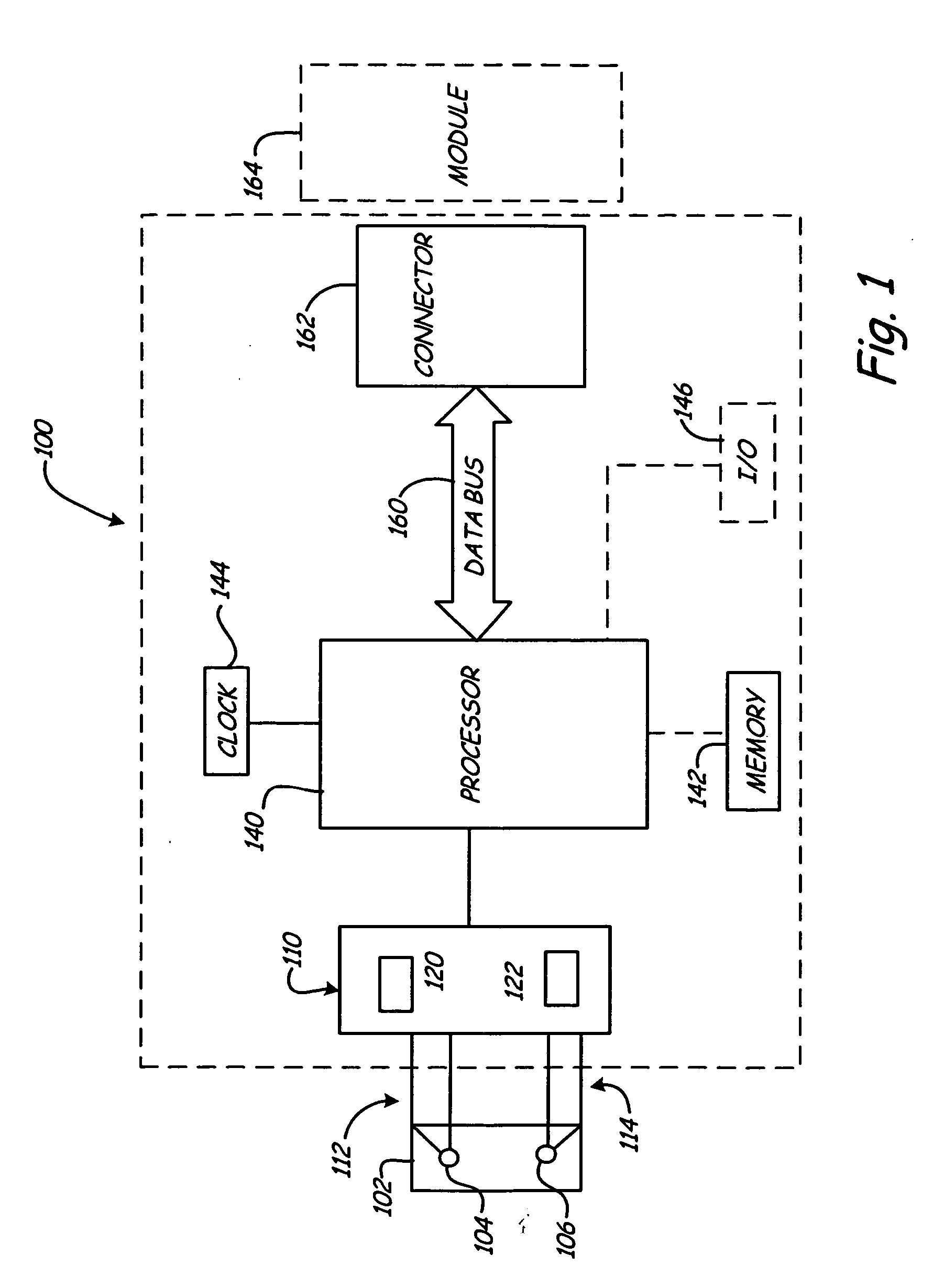
[0012]FIG. 1 is a simplified diagram of a battery tester 100 configured to test a storage battery 102. Storage battery 102 includes terminals 104 and 106 and may comprise a single cell or a plurality of cells. Battery tester 100 includes batter...
PUM
 Abstract
Description
Claims
Application Information