Electrostatic fly-height control

a technology of electric fly-height control and slider, which is applied in the direction of magnetic recording, data recording, instruments, etc., can solve the problems of bouncing vibrations, small components of small drives with very narrow tolerances, and most computing systems are not operational

Inactive Publication Date: 2008-11-11
WESTERN DIGITAL TECH INC
View PDF12 Cites 53 Cited by
  • Summary
  • Abstract
  • Description
  • Claims
  • Application Information

AI Technical Summary

Problems solved by technology

In fact, most computing systems are not operational without some type of hard disk drive to store the most basic computing information such as the boot operation, the operating system, the applications, and the like.
However, the small drives have small components with very narrow tolerances.
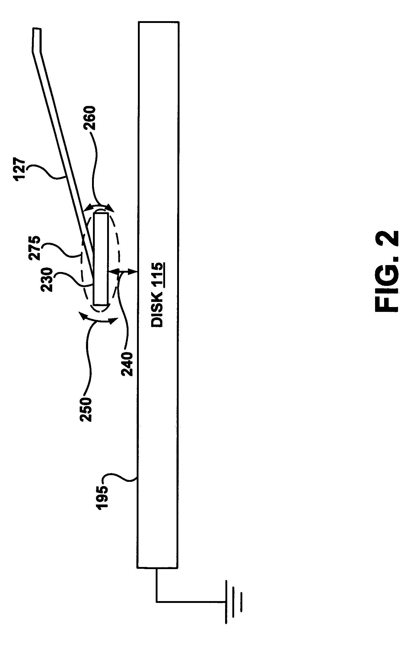
These forces alone, and in combination, create bouncing vibrations of the slider which contribute to undesirable fluctuations of the fly-height of the slider.
Bouncing vibrations of the slider are undesirable because they can cause media damage.
Bouncing vibrations also cause variations in the magnetic spacing between the head element and media (due to fluctuations in fly-height) that are likely to cause data errors—both hard errors during writing and soft errors during reading.

Method used


Image

  • Electrostatic fly-height control
  • Electrostatic fly-height control
  • Electrostatic fly-height control

Examples


Embodiment Construction

[0017]Reference will now be made in detail to the alternative embodiments of the present technology. While of the present technology will be described in conjunction with the alternative embodiments, it will be understood that they are not intended to limit the present technology to these embodiments. On the contrary, embodiments of the present technology are intended to cover alternatives, modifications and equivalents, which may be included within the spirit and scope of the embodiments as defined by the appended claims.

[0018]Furthermore, in the following detailed description, numerous specific details are set forth in order to provide a thorough understanding of embodiments of the present technology. However, it will be recognized by one of ordinary skill in the art that embodiments may be practiced without these specific details. In other instances, well known methods, procedures, components, and circuits have not been described in detail as not to unnecessarily obscure aspects ...


PUM

PropertyMeasurementUnit
diameteraaaaaaaaaa
diametersaaaaaaaaaa
center frequencyaaaaaaaaaa

Abstract

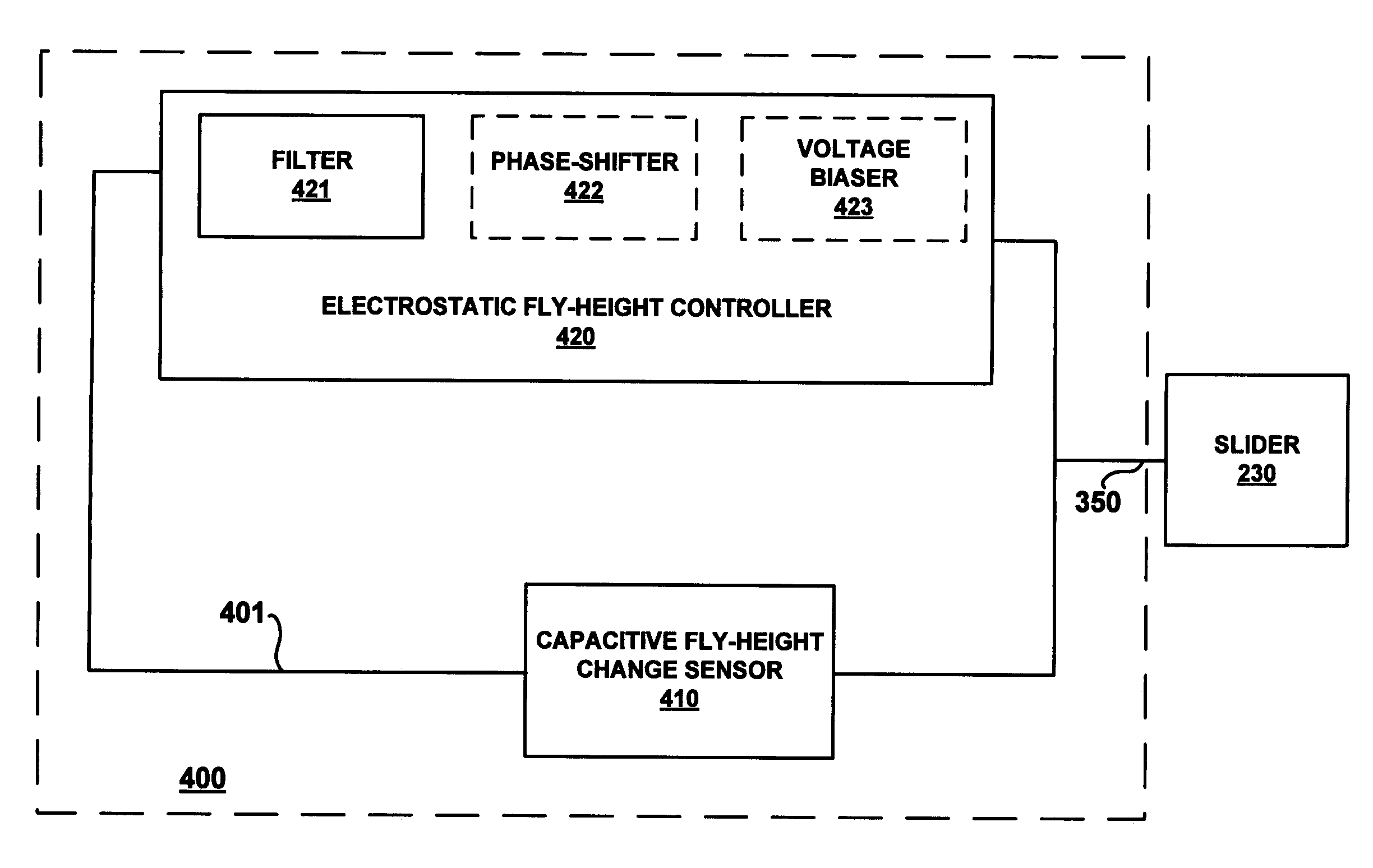
A mechanism for maintaining a constant fly-height of a slider comprises a capacitive fly-height change sensor and an electrostatic fly-height controller. The capacitive fly-height change sensor is configured for coupling with the slider, which is in a head gimbal assembly. The capacitive fly-height change sensor is also configured for measuring a capacitance between the slider and a surface of a disk through the use of a fly-height change sensing signal, and outputting a sensor voltage which is substantially proportional to a sensed change in said capacitance. The electrostatic fly-height controller is coupled with the capacitive fly-height change sensor and configured to couple with the slider. The electrostatic fly-height controller is configured to process the sensor voltage into a fly-height control signal for electrostatically maintaining a constant fly-height of the slider relative to the surface of the disk.

Description

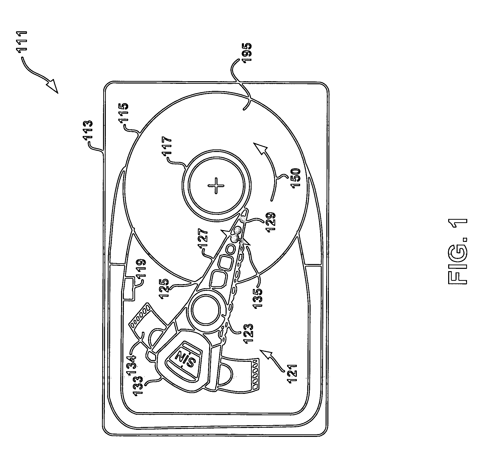
TECHNICAL FIELD[0001]Embodiments of the present technology relate to the field of hard disk drive development and slider fly-height control.BACKGROUND ART[0002]Hard disk drives are used in almost all computer system operations. In fact, most computing systems are not operational without some type of hard disk drive to store the most basic computing information such as the boot operation, the operating system, the applications, and the like. In general, the hard disk drive is a device which may or may not be removable, but without which the computing system will generally not operate.[0003]The basic hard disk drive model includes a storage disk or hard disk that spins at a designed rotational speed. An actuator arm with a suspended slider is utilized to reach out over the disk. The slider is coupled with a suspension that supports both the body of the slider and a head assembly that has a magnetic read / write transducer or head or heads for reading / writing information to or from a loc...

Claims


Application Information

Patent Timeline
Patent Type & Authority Patents(United States)
IPC IPC(8): G11B21/02G11B21/24
CPCG11B5/6005G11B5/6035G11B5/6017
Inventor HIRANO, TOSHIKIKNIGGE, BERNHARD E.
Owner WESTERN DIGITAL TECH INC
Why Eureka
Try Eureka