Method and device for airborne laser scanning flying height change real-time compensation

A technology of airborne laser scanning and flying height, which is applied in the direction of measuring devices, using re-radiation, re-radiation of electromagnetic waves, etc., can solve the problems that the flight height cannot be compensated for, and does not change, so as to eliminate adverse effects, improve quality and high The effect of precision real-time compensation

Inactive Publication Date: 2013-04-10
SHANDONG UNIV OF TECH
View PDF3 Cites 53 Cited by
  • Summary
  • Abstract
  • Description
  • Claims
  • Application Information

AI Technical Summary

Problems solved by technology

[0006] Aiming at the defect that the existing measurement technology of the above-mentioned airborne laser radar system cannot compensate the change of flight height, the present invention provides a method and device for real-time compensation of flig

Method used


Image

  • Method and device for airborne laser scanning flying height change real-time compensation
  • Method and device for airborne laser scanning flying height change real-time compensation
  • Method and device for airborne laser scanning flying height change real-time compensation

Examples


Embodiment Construction

[0024] The patent embodiments of the present invention will be further described in detail below in conjunction with the accompanying drawings.

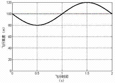
[0025] figure 1 is the flight altitude change map. The change of flight height is a sinusoidal change with an amplitude of 20 meters and a period of 2 seconds.

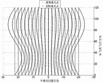
[0026] figure 2is the influence diagram of the flight altitude change on the distribution bandwidth and density of the ground laser scanning point cloud. The compensation technology for flight height changes is suitable for laser scanning systems of airborne platforms such as low-altitude and low-speed small hang glider aircraft or helicopters, airships, and small fixed-wing aircraft. The adverse effects of the point cloud scanning bandwidth and density are always kept constant, ensuring the quality of 3D reconstruction models (such as DSM and DEM). Such as figure 2 Shown is the distribution change of the ground laser scanning point cloud when the flight height remain...


PUM


Abstract

A method and a device for airborne laser scanning flying height change real-time compensation can eliminate adverse effect of flying height change to a laser scanning point cloud distribution area and cloud density of a laser scanning point. When the flying height of an airborne platform is changed, a flying height change value is acquired by a global position system(GPS)/ inertial navigation system(INS)integrated measurement device, the value of a scan field angle which can keep the width of a scanning stripe unchanged and the value of a laser pulse frequency which can keep the laser scanning point cloud density unchanged are calculated in a flying height compensation controller. A rotating prism photoelectric shaft angle encoder measures and obtains a real time rotating angle of a rotating prism and offers the real time rotating angle of the rotating prism to the flying height compensation controller, a square signal which is identical with an expect laser pulse frequency value is outputted only within a scope of the required scan field angle and offered to a laser pulse transmitter, thus a laser transmitter can launch a laser pulse of the corresponding frequency. By using the compensation method, the flying height change of the airborne platform can not affect the laser scanning point cloud distribution area and cloud density of a laser scanning point permanently.

Description

technical field [0001] The invention relates to the compensation problem of the flying height change of the point-scanning three-dimensional imaging airborne laser radar. Background technique [0002] Airborne lidar is a terrain mapping technology based on the principle of laser ranging, which integrates aircraft platforms, laser scanners, differential global positioning system DGPS (Differential Global Positioning System), inertial navigation system INS (Initial Navigation System) and computer data acquisition and processing system, etc. [0003] The working process of the airborne lidar is as follows: the aircraft flies in a straight line at a constant speed on a preset flight route, and the flight altitude is planned in advance. In the local horizontal plane reference coordinate system, the ideal flight altitude is unchanged. The track and attitude angle of the laser scanner load platform are measured in real time by the DGPS / INS combined measurement system through Kalma...

Claims


Application Information

Patent Timeline
IPC IPC(8): G01S7/497G01S17/89
Inventor 王建军许同乐李东兴
Owner SHANDONG UNIV OF TECH
Why Eureka
Try Eureka