Spa jet with screw in jet barrel

a jet barrel and screw technology, applied in the field of spa jets, can solve the problems of the internals of the jet, in particular the clips, to fail

Active Publication Date: 2013-06-11
GUANGZHOU RISING DRAGON RECREATION IND CO LTD
View PDF78 Cites 7 Cited by
  • Summary
  • Abstract
  • Description
  • Claims
  • Application Information

AI Technical Summary

Benefits of technology

[0005]Generally, the present invention provides an improved rotatable connection between the jet internals and jet body that solves the aforementioned jet internal failure problems while continuing to enable full control of open / close of water flow by rotation of the jet internals.

Problems solved by technology

Currently, an existing problem with the conventional jet assemblies is that the jet internals, in particular the clips, tend to fail by popping out of the jet body over time due to continuous vibration, chemical corrosion, raw material limitations and high water pressure.

Method used


Image

  • Spa jet with screw in jet barrel
  • Spa jet with screw in jet barrel
  • Spa jet with screw in jet barrel

Examples


Embodiment Construction

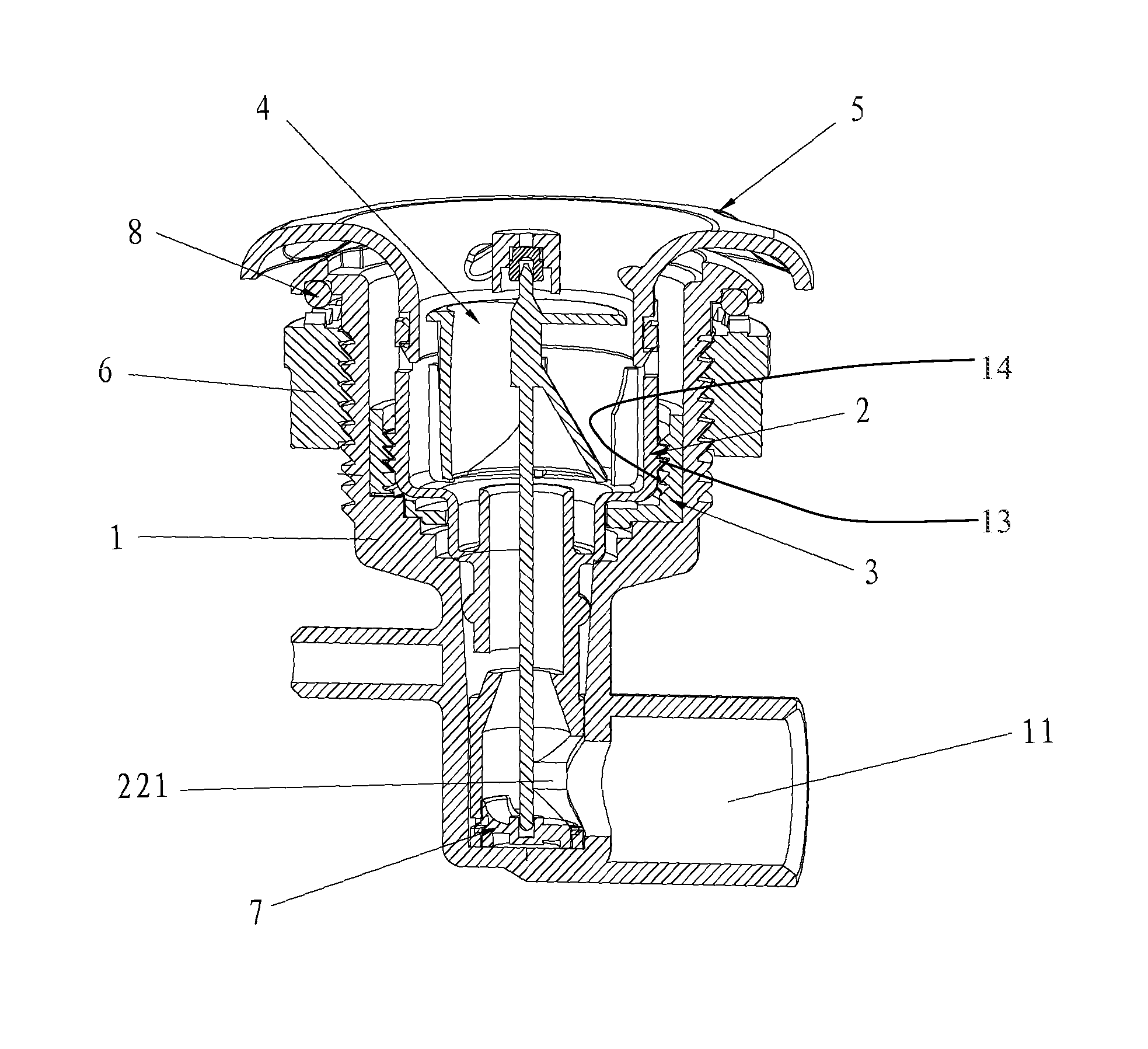
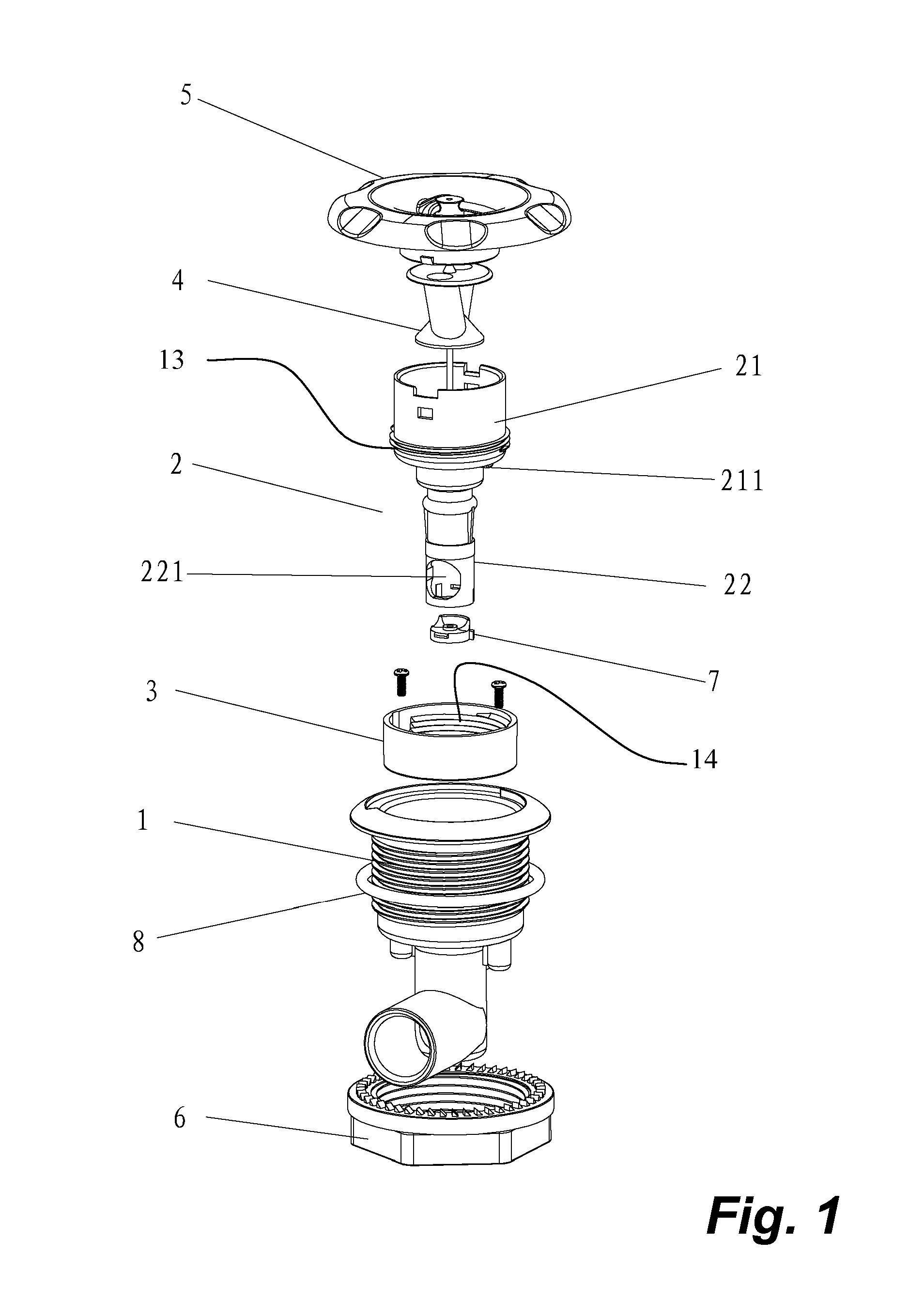
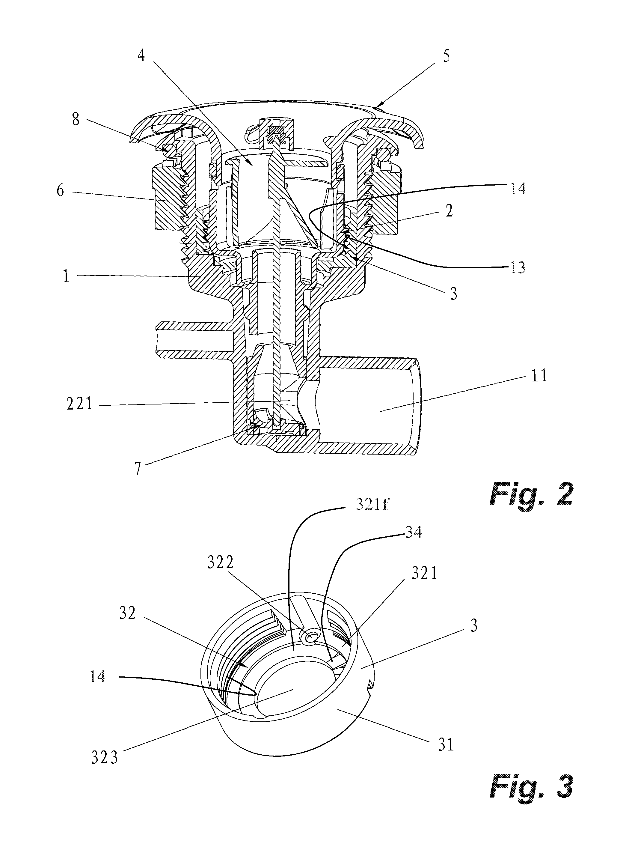
[0018]FIGS. 1 and 2 illustrate a spa jet having jet internals comprising face 5, rotor 4, barrel housing or barrel 2, and a barrel end piece 7. Further, the spa jet comprises a jet body 1 fit with a lock ring 3, the jet body being adapted for support in a spa by an O-ring 8 and nut 6. The lock ring 3 is installed in the jet body 1. The face 5 and the barrel 2 are fixed together. Barrel 2 comprises a barrel cavity 21 for housing a rotor 4 supported rotatably therein by means such as a spindle pin, and a barrel inlet or lower inlet end 221 for receiving a flow of water from the jet body 1.

[0019]The jet internals are rotatably mounted within the jet body 1. A cooperating threaded connection having a first threaded portion 13 outside of the barrel 2 and a second threaded portion 14 inside the lock ring 3 for screwing in or rotatably securing the barrel 2 to the jet body 1. The first threaded portion 13 can be about the barrel cavity 21. Once threaded together, cooperating, rotational de...


PUM


Abstract

A jet assembly has internals rotatably and releaseably fit to a jet body, such as that for a spa. The internals have a barrel housing, a rotor and a barrel inlet. The internals as screwed into the jet body. A first threaded portion outside the barrel threadably engages second threaded portion inside the jet body wherein the internals have delimited rotation therein to align and misalign the barrel inlet from a body inlet on the jet body to control flow on and off respectively. The threaded portion within the jet body can be a locking ring affixed therein by fasteners or integral with the jet body. Rotation can be delimited by a projection on the barrel and a cooperating annular delimiting surface on the locking ring, such as circumferentially-spaced detents.

Description

FIELD OF THE INVENTION[0001]The invention relates to spa jets used in spas, pools or any other hydrotherapy equipment and more particularly relates to spa jets having a jet barrel releasably and threadably affixed in a jet body.BACKGROUND OF THE INVENTION[0002]A conventional jet assembly includes a removable jet internals including a face, a rotor, a barrel, and a barrel end piece. The jet internals are removeably fit to a jet body. A lock ring is installed inside the jet body. The face and barrel are fixed together. Spring clips extending from barrel join to the lock ring. Inlet ports on an end of the barrel cooperate with the jet body to enable on / off the flow when the jet internals are rotated. Further, air is automatically drawn in via an air-inlet port on jet body by a venturi action.[0003]Currently, an existing problem with the conventional jet assemblies is that the jet internals, in particular the clips, tend to fail by popping out of the jet body over time due to continuous...

Claims


Application Information

Patent Timeline
Patent Type & Authority Patents(United States)
IPC IPC(8): B05B1/02A61H33/00A47K3/10E04H4/12
CPCA61H33/6063
Inventor PENG, XUE WENKEIRSTEAD, JOHNHARBARENKO, KERRYHOOVER, JOELIU, XUE WEN
Owner GUANGZHOU RISING DRAGON RECREATION IND CO LTD
Why Eureka
Try Eureka