
Agricultural corn sheller

A corn threshing and crushing device technology, applied in threshing equipment, application, agriculture, etc., can solve problems such as insufficient separation of corn cobs and reduction of environmental quality

Active Publication Date: 2019-03-26
唐山观畴科技有限公司
View PDF10 Cites 1 Cited by
  • Summary
  • Abstract
  • Description
  • Claims
  • Application Information

AI Technical Summary

Problems solved by technology

[0002] For example, the patent number is CN201621393270.4, an agricultural corn threshing device, including a frequency conversion motor, a threshing bin, a control panel, a human body pyroelectric infrared sensor, a suction fan and a solar photovoltaic power generation unit, and one side of the threshing bin is connected with a transfer bin , the threshing bin is connected to the bottom of the threshing bin, and the bottom side of the threshing bin is provided with a corn grain outlet, the frequency conversion motor is arranged on the inner side of the main body of the device, and the threshing shaft and the screen are both arranged in the threshing bin The inner cavity of the delivery bin, the feeding hopper is connected to one side of the transfer bin, and a control panel is inlaid on the outer wall of the transfer bin, the human body pyroelectric infrared sensor is embedded in the inner cavity of the transfer bin, and the suction fan is set at One side of the main body of the device, but the disadvantage of this invention is that only one screening is performed, so that the separation of corn kernels and crushed corn cobs is not sufficient. In addition, whether the separated corn cobs in this invention has a collection device will easily reduce the quality of the environment

Method used


Image

  • Agricultural corn sheller
  • Agricultural corn sheller
  • Agricultural corn sheller

Examples


specific Embodiment approach 1

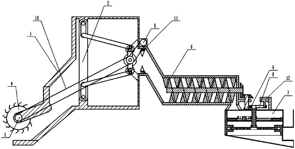
[0032] Combine below Figure 1-15 Describe this embodiment, an agricultural corn threshing device, including a frame assembly 1, an auxiliary push rod assembly 2, a push roller pulley 3, a push roller 4, an input motor 5, a crushing device 6, a screening device 7, and a transmission belt One 8, transmission belt two 9, connecting belt one 10, connecting belt two 11 and right side motor 12, it is characterized in that: the frame assembly 1 is fixedly connected with the auxiliary push rod assembly 2, and the push stick pulley 3 is connected with the push rod assembly 2. The stick 4 is fixedly connected, the push stick 4 is connected to the frame assembly 1 in rotation, the input motor 5 is fixedly connected to the crushing device 6, the crushing device 6 is fixedly connected to the frame assembly 1, the screening device 7 is fixedly connected to the crushing device 6, The transmission belt one 8 is connected between the right motor 12 and the screening device 7, the transmission...

specific Embodiment approach 2

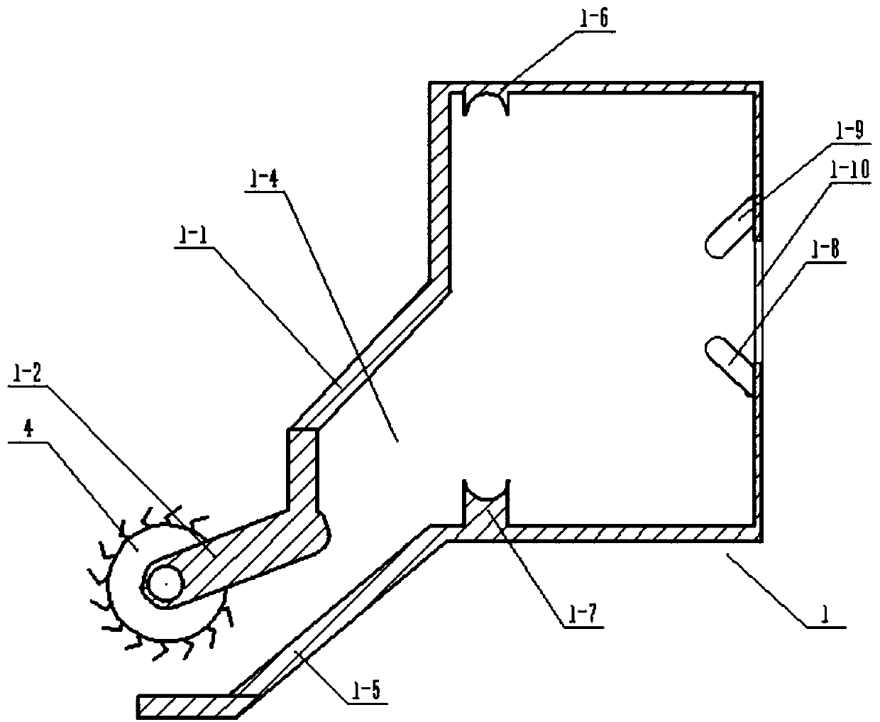
[0033] Combine below Figure 1-15 Describe this embodiment, this embodiment will further explain Embodiment 1, the frame assembly 1 includes a frame body 1-1, a push stick bracket 1-2, a frame inner cavity 1-4, and a lower end plate 1 -5, upper side hinged fixing frame 1-6, lower side hinged fixing frame 1-7, lower side hinged connecting frame 1-8, upper side hinged connecting frame 1-9 and rack outlet 1-10, push the stick The bracket 1-2 is fixedly connected to the left end of the rack body 1-1, the rack inner cavity 1-4 is arranged at the inner end of the rack body 1-1, and the lower end plate 1-5 is fixedly connected to the rack body 1-1. 1 The lower side of the left end, the upper side hinged fixing frame 1-6 and the lower side hinged fixing frame 1-7 are respectively fixedly connected to the upper and lower sides of the inner wall of the frame cavity 1-4, the lower side hinged connecting frame 1-8 and the upper side The side hinged connecting frames 1-9 are respectively ...

specific Embodiment approach 3

[0034] Combine below Figure 1-15 Describe this embodiment, this embodiment will further explain Embodiment 1, the auxiliary push rod assembly 2 includes an auxiliary frame 2-1, a lower gear 2-2, an auxiliary transmission pulley 2-3, a middle end gear 2- 4. Upper gear 2-5, lower hinged rod 2-6, lower hinged terminal 2-7, left hinged rod 2-8, upper hinged rod 2-9, upper hinged terminal 2-10, upper Side extrusion plate 2-11, two sawtooth push plates 2-12, two push springs 2-13, threaded sleeve 2-14, threaded rotating rod 2-15, rear side hinged pole 2-16 and two The expansion plate 2-17, the upper side extrusion plate 2-11 includes the upper side extrusion plate body 2-11-1, the extrusion plate main chamber 2-11-2, four sleeves 2-11-3 and The spring sleeve 2-11-4, the main cavity 2-11-2 of the extrusion plate is arranged at the inner end of the upper extrusion plate body 2-11-1, and the main cavity 2-11-2 of the extrusion plate does not penetrate the upper Side extrusion plate ...


PUM


Abstract

The invention relates to an agricultural machine, and concretely relates to an agricultural corn sheller. Secondary separation of corn is carried out through a screening device, so the corn kernels and crushed corncobs are separated sufficiently; the screening device is arranged at a foreign material discharging port, so foreign materials can be easily collected, and the environmental quality is easily improved; and the corncob transportation capacity of an auxiliary push rod assembly can be easily changed, so the efficiency of the machine is easily improved. The agricultural corn sheller includes a frame assembly, the auxiliary push rod assembly, a push rod belt wheel, a push rod, an input motor, a crusher, the screening device, a driving belt 1, a driving belt 2, a connecting belt 1, a connecting belt 2 and a right motor, and the upper end and the lower end of a left hinged support rod can be conveniently fixedly connected to an upper hinged fixed frame and a lower hinged fixed frame; an upper hinged connecting frame and the discharging port of the frame are conveniently fixedly connected to the upper side and the lower side of the right end surface of an auxiliary frame; and a pushing rod shaft can be conveniently fixedly connected to the front end of a pushing rod body.

Description

technical field [0001] The invention relates to an agricultural machine, in particular to an agricultural corn threshing device. Background technique [0002] For example, the patent number is CN201621393270.4, an agricultural corn threshing device, including a frequency conversion motor, a threshing bin, a control panel, a human body pyroelectric infrared sensor, a suction fan and a solar photovoltaic power generation unit, and one side of the threshing bin is connected with a transfer bin , the threshing bin is connected to the bottom of the threshing bin, and the bottom side of the threshing bin is provided with a corn grain outlet, the frequency conversion motor is arranged on the inner side of the main body of the device, and the threshing shaft and the screen are both arranged in the threshing bin The inner cavity of the delivery bin, the feeding hopper is connected to one side of the transfer bin, and a control panel is inlaid on the outer wall of the transfer bin, th...

Claims


Application Information

Patent Timeline
Patent Type & Authority Applications(China)
IPC IPC(8): A01F11/06A01F12/40A01F12/44A01F12/56
CPCA01F11/06A01F12/40A01F12/446A01F12/56
Inventor 吴燕红
Owner 唐山观畴科技有限公司
Learn More