Biological-tissue joining apparatus

a technology of tissue and joining apparatus, applied in the field of tissue joining apparatus, can solve the problems of inability to apply immediate treatment, decreased flexibility, and difficulty in maintaining a stable joined state, and achieve the effect of preventing the inability to apply adhesiv

Active Publication Date: 2013-06-11
OLYMPUS CORP
View PDF27 Cites 269 Cited by
  • Summary
  • Abstract
  • Description
  • Claims
  • Application Information

AI Technical Summary

Benefits of technology

[0012]It is an object of the present invention to provide a biological-tissue treating apparatus that, regardless of the type of biological tissue, is capable of immediately obtaining a sufficient joining force, preventing a problem of an adhesive bonding biological tissue other than the target biological tissue, and preventing the inability to apply the adhesive due to curing.

Problems solved by technology

HEI-11-104143 by merely clamping and supplying ultrasonic energy to the biological tissue, in some cases, it may be difficult to maintain a stable joined state of the joined biological tissue because a sufficient joining force is not obtained due to individual differences of the biological tissue, or the flexibility may decrease because of hardening of the biological tissue after joining.
With the apparatus in Japanese Unexamined Patent Application, Publication No. 2001-54523, the sites that can be cut may be limited to small sites with a small vascular diameter since efficient hemostasis cannot be carried out because temperature rises only locally with clotting by ultrasound.
Furthermore, such as in Japanese Unexamined Patent Applications, Publication Nos. 2003-235977 and 2006-110357, immediate treatment may not be carried out because curing of the adhesive in the joining area takes time when a biological adhesive is merely applied.
When the operation of bonding a joining site is carried out repeatedly by applying an adhesive, in some cases, the adhesive gradually cures inside a supply channel, and thus a sufficient amount of adhesive cannot be applied.
When a joining site is bonded by applying an adhesive, in some cases, tissue other than the target tissue may be bonded because the adhesive spatters, is applied excessively, and / or remains uncured when the adhesive is a two-component mixing type.

Method used


Image

  • Biological-tissue joining apparatus
  • Biological-tissue joining apparatus
  • Biological-tissue joining apparatus

Examples


Embodiment Construction

[0101]A biological-tissue processing apparatus 1 according to an embodiment of the present invention will be described below with reference to the drawings.

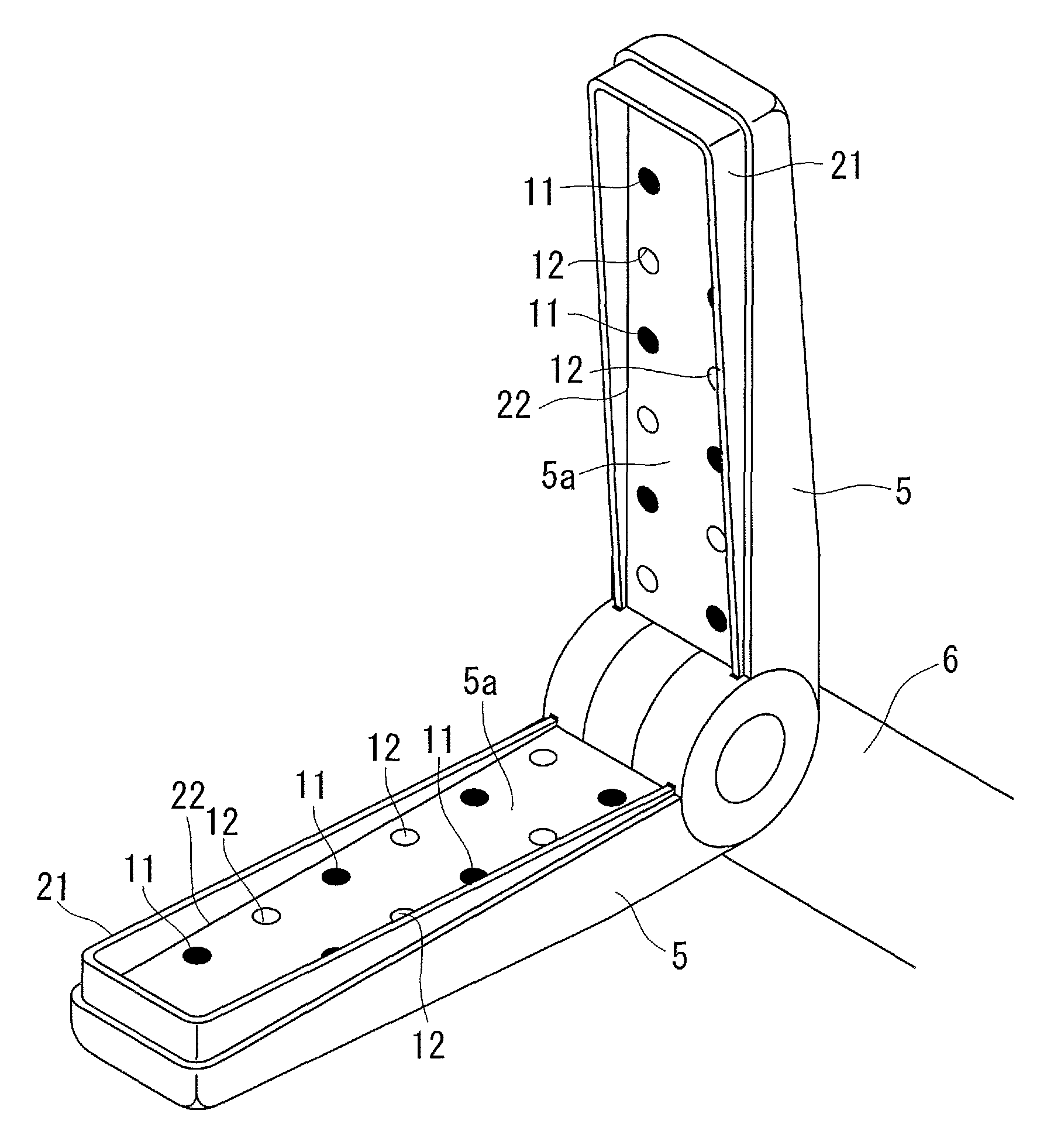
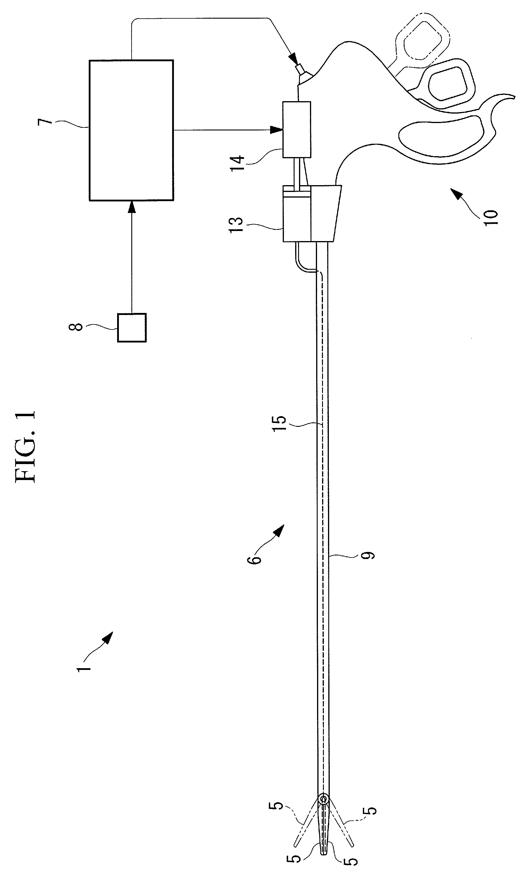
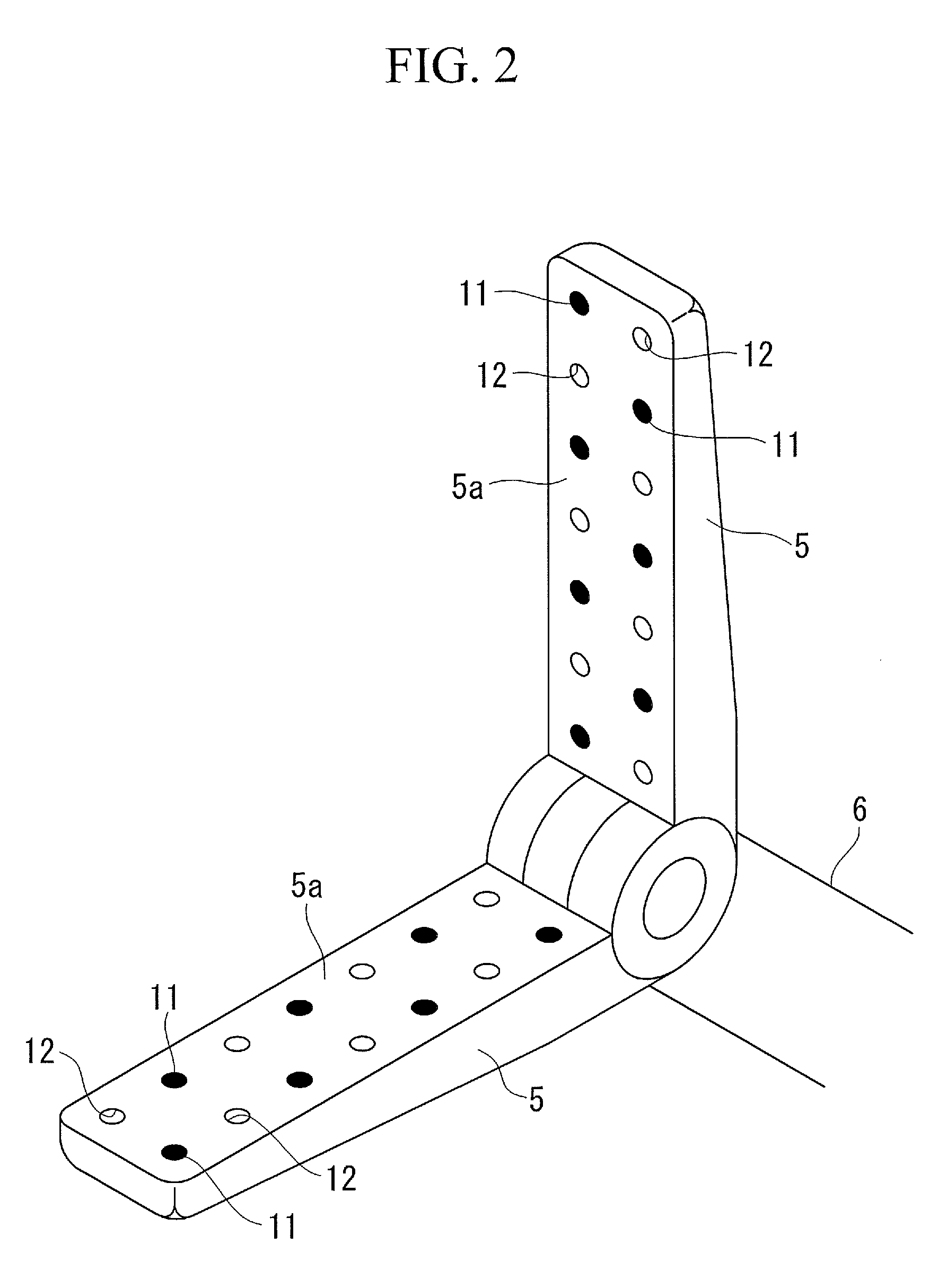
[0102]The biological-tissue processing apparatus 1 of this embodiment, which is a biological-tissue joining apparatus (herein after also referred to as biological-tissue joining apparatus 1), is, as shown in FIG. 1, an apparatus for anastomosing biological tissue such as intestinal tracts 2 and 3, which are tubular biological tissue, as shown in FIGS. 6 to 11, and includes an apparatus main body 6 having a pair of electrodes 5 that clamp the intestinal tracts 2 and 3 from the outer radial direction so as to cover joined ends 2a and 3a of the pair of intestinal tracts 2 and 3, which are pressed together with a tubular anastomosing member 4 described below, a control unit 7 connected to the apparatus main body 6, and a switch 8 connected to the control unit 7.

[0103]The apparatus main body 6 includes the electrodes 5 provided at the...


PUM


Abstract

Regardless of the type of biological tissue, a sufficient joining force can be quickly obtained; the problem of an adhesive bonding biological tissue other than the target biological tissue can be prevented; and the adhesive can be prevented from becoming impossible to apply due to curing. There is provided a biological-tissue joining apparatus including an energy supplying part that clamps, with pressure, biological tissue to be joined and melts protein in the clamped biological tissue by supplying energy to the biological tissue; and an adhesive supplying part that supplies an adhesive to the biological tissue, wherein the adhesive supplying part includes a discharge port that discharges the adhesive to a contact surface of the energy supplying part in contact with the biological tissue.

Description

BACKGROUND OF THE INVENTION[0001]1. Field of the Invention[0002]The present invention relates to a biological-tissue joining apparatus.[0003]This application is based on Japanese Patent Applications Nos. 2007-150684, 2009-248163, and 2009-258169 the content of which is incorporated herein by reference.[0004]2. Description of Related Art[0005]Conventionally, there is a known joining apparatus that joins biological tissue by clamping a stacked pair of pieces of biological tissue and applying ultrasonic energy (for example, refer to Japanese Unexamined Patent Application, Publication No. HEI-11-104143). Moreover, there is a known ultrasonic incising apparatus that is capable of carrying out clotting, cutting, and hemostasis of biological tissue for surgery, such as abdominal surgery or endoscopic surgery, at a temperature lower than an electrosurgical knife and capable of simultaneously carrying out hemostasis and incising (for example, refer to Japanese Unexamined Patent Application, ...

Claims


Application Information

Patent Timeline
Patent Type & Authority Patents(United States)
IPC IPC(8): A61B18/18
CPCA61B17/00491A61B18/1445A61B2017/00504A61B2017/00513A61B2018/00494
Inventor TAMAI, MASATOHORII, AKIHIROKAKIDACHI, HIROSHIHAYASHI, MASAKIOKUBO, AKITAKAHASHI, HIROSHI
Owner OLYMPUS CORP
Why Eureka
Try Eureka