Bone plate

a bone plate and plate hole technology, applied in the field of bone plate fixation, can solve the problems of low angular stability of known bone plate holes, high-energy trauma of proximal humerus fracture,

Inactive Publication Date: 2013-06-11
DEPUY SYNTHES PROD INC
View PDF13 Cites 12 Cited by
  • Summary
  • Abstract
  • Description
  • Claims
  • Application Information

AI Technical Summary

Benefits of technology

The present invention is a bone plate used for fixating fractures, particularly in the proximal humerus. It is designed to provide stable osteosynthesis and can be used on both sides of the body. The bone plate has a shaft portion and a head portion with a screw hole for attaching a bone screw. The technical effects of this invention include achieving better outcomes, reduced complications, and improved functional outcome in patients with proximal humerus fractures.

Problems solved by technology

In recent years, a common cause of fractures of the proximal humerus has been high-energy trauma.
One disadvantage of this type of bone plate is that the hole configuration of the head portion may inhibit inserting screws into the intact bone structure located at the edge zone of the proximal humerus.
Moreover, the known bone plates may lack angularly stable options in the plate holes.
Under dynamic conditions, the axial pressure applied on the bone screws may cause the bone screws to tear out of the bone, and may result in a loss of the stability of the plate-bone construct.
The prior art surgical technique of using blades, however, requires greater time expenditure and is complex to use.

Method used


Image

  • Bone plate
  • Bone plate
  • Bone plate

Examples


Embodiment Construction

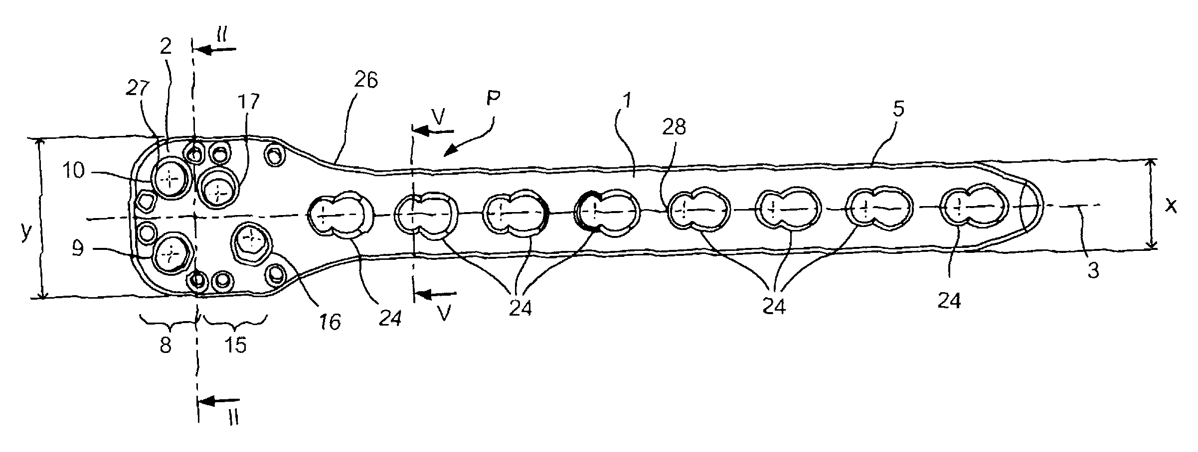
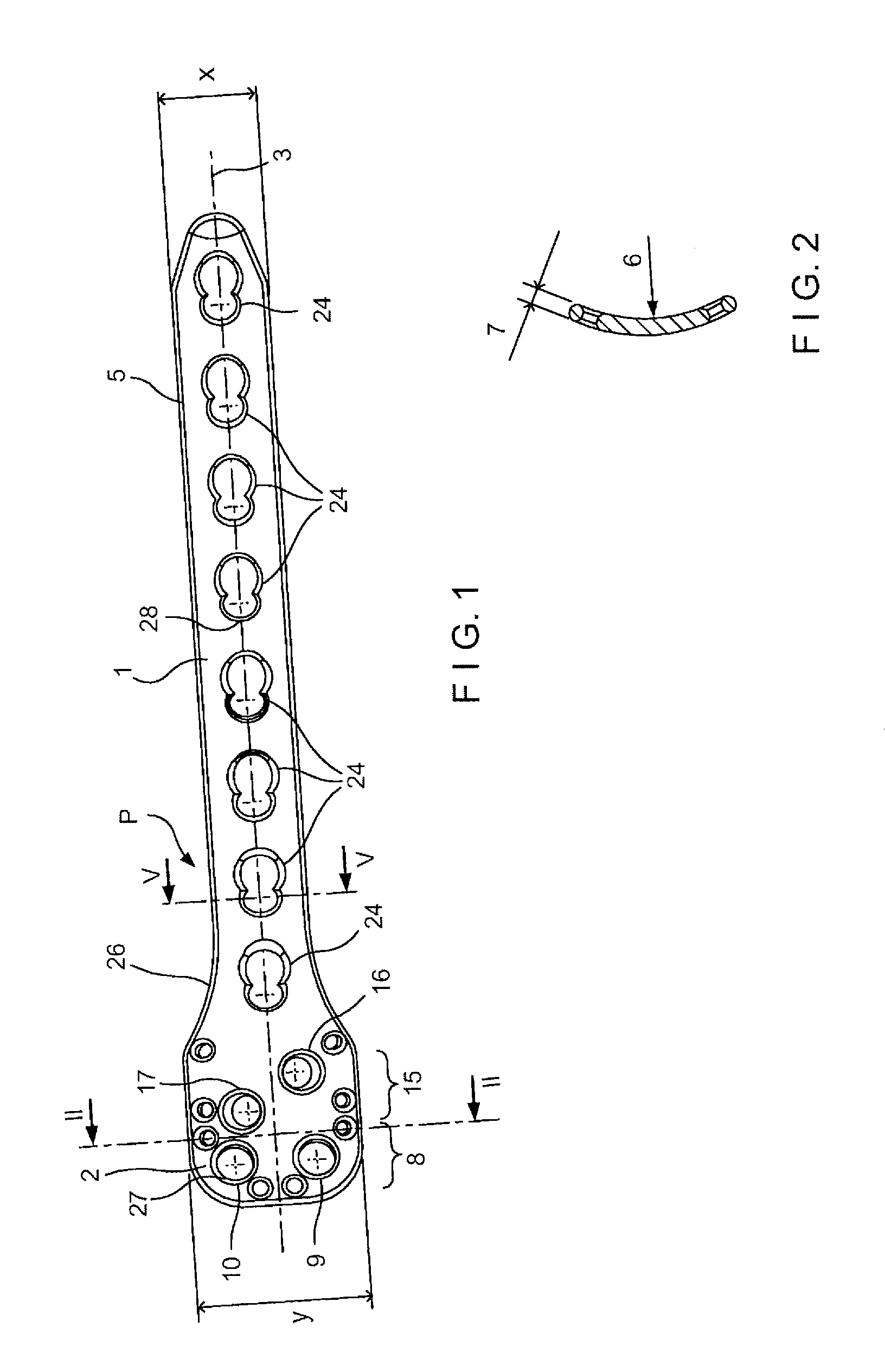
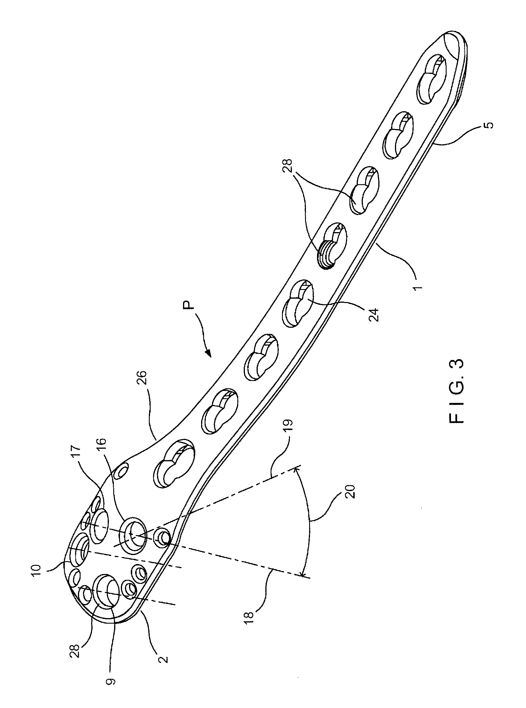
[0021]Referring to FIGS. 1 to 4, an illustrative embodiment of a bone plate according to the present invention is shown. Bone plate P may be used for fixation of the long bones, such as, for example, fixation of the proximal humerus. Plate P may include an elongated shaft I having a length greater than its width x. Plate P may also have a head 2, preferably spoon-shaped, with a width y which is greater than the width x of the elongated shaft 1. The elongated shaft 1 and the head 2 may have a common longitudinal axis 3 and may be interconnected by a transition area 26. Transition area 26 may widen from the width x of the elongated shaft 1 to the width y of the head 2. According to one preferred embodiment, transition area 26 may widen exponentially from width x to width y.

[0022]A large number of screw holes 9, 10, 16, 17, and 24 may be located in the elongated shaft 1 and in the head 2. In one preferred embodiment, the screw holes 24 provided in the elongated shaft 1 may have an insi...


PUM


Abstract

A bone plate for fixation of proximal humerus fractures comprises an elongated shaft portion having a first width and a head portion connected to the shaft portion having a second width greater than the first width. The head portion and the shaft portion define a common longitudinal axis. At least one first screw hole may be located in the head portion, and at least one second screw hole may be located in the shaft portion. At least one of the first and second holes is configured to engage a head of a bone screw to form an angularly stable connection with the bone screw.

Description

CROSS-REFERENCE TO RELATED APPLICATIONS[0001]The present application is a Continuation Application of U.S. patent application Ser. No. 10 / 721,895 filed on Nov. 26, 2003, which is a continuation of the U.S. National Stage designation of copending International Patent Application No. PCT / CH01 / 00327, filed May 28, 2001, the entire content of which is expressly incorporated herein by reference thereto.TECHNICAL FIELD OF THE INVENTION[0002]The present invention relates generally to bone plates for fixation of long bones. More specifically, the present invention relates to bone plates for fixation of multiple-part and dislocated fractures of the long bones, such as those of the proximal humerus.BACKGROUND OF THE INVENTION[0003]In recent years, a common cause of fractures of the proximal humerus has been high-energy trauma. The occurrence of this type of fracture increases with age because the bone structure in the area of the proximal humerus degrades over time, such that only the edge zo...

Claims


Application Information

Patent Timeline
Patent Type & Authority Patents(United States)
IPC IPC(8): A61B17/80A61B17/58A61F2/28
CPCA61B17/8057A61B17/8061A61B17/68
Inventor NIEDERBERGER, ALFREDHATTLER, ERIC
Owner DEPUY SYNTHES PROD INC
Why Eureka
Try Eureka