Pipe guide arms for blind shear rams

a technology of blind shear rams and guide arms, which is applied in the direction of drilling pipes, drilling casings, borehole/well accessories, etc., can solve the problem of incomplete shearing of pipe strings

Active Publication Date: 2013-06-18
HYDRIL USA DISTRIBUTION LLC
View PDF15 Cites 8 Cited by
  • Summary
  • Abstract
  • Description
  • Claims
  • Application Information

AI Technical Summary

Benefits of technology

[0007]Each of the blades may have a length between outboard ends that is less than a diameter of the bore. A pair of recesses are located on the second ram block adjacent opposite ends of the blade of the second ram block for receiving the guide arms when the first and second ram blocks move to the closed position. Each of the recesses has an upper wall. The guide arms are mounted to the first ram block so as to avoid sliding contact with the upper walls as the ram blocks move to the closed position. The bottoms and outboard sides of the recesses may be open. In one embodiment, the blade of the first ram block slides over the blade of the second ram block when in the closed position.

Problems solved by technology

In some pipe ram assemblies, a remote possibility exists that the pipe string will remain at an outside wall of the bore during closure, which could lead to incomplete shearing of the pipe string.

Method used


Image

  • Pipe guide arms for blind shear rams
  • Pipe guide arms for blind shear rams
  • Pipe guide arms for blind shear rams

Examples


Embodiment Construction

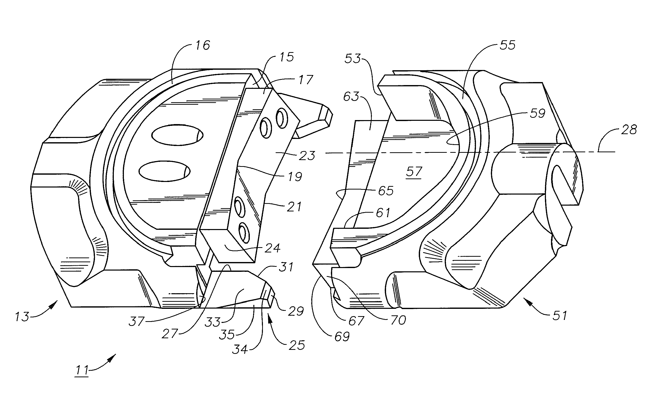
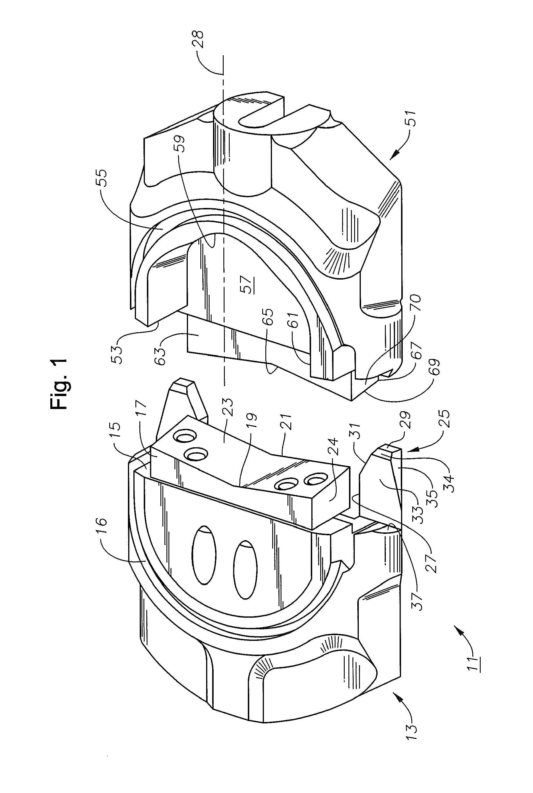
[0016]Referring to FIG. 1, shear rams 11 are shown removed from the housing or bonnet in which they are located. Shear rams 11 are part of a ram BOP assembly that is part of a stack assembly. In the case of offshore drilling, the stack assembly is located at the lower end of a riser extending downward from a drilling vessel. The lower end of the BOP stack assembly secures to a subsea wellhead on the sea floor. The BOP stack assembly will normally also contain pipe rams, variable bore rams, and a quick disconnect mechanism for disconnecting from the riser in the event of an emergency. When actuated, shear rams 11 will close the through bore and also shear pipe in the well, such as drill pipe, tubing, or casing.

[0017]Shear rams 11 include an upper ram assembly 13 having a face or forward end 15. A semi-circular seal groove 16 is located on the upper side of upper ram block13 for receiving a portion of an elastomeric seal. An upper shearing blade 17 mounts to forward end 15. Upper blad...


PUM


Abstract

A pipe shear ram assembly has a housing having a bore extending vertically therethrough for the passage of a pipe string. Ram blocks have blades positioned such that one slides over the other when the first and second ram blocks are moved toward each other to shear a well pipe. A pair of guide arms extend from one of the rams. The guide arms have tips protruding a greater distance than the blade. Each of the guide arms has an inboard wedge surface beginning at the tip and extending along a line that intersects the longitudinal axis for guiding the pipe string toward a bore axis of the bore in the event the first and second ram blocks are moved to the closed position.

Description

CROSS-REFERENCE TO RELATED APPLICATION[0001]This application claims priority to provisional application Ser. No. 61 / 496,835, filed Jun. 14, 2011.FIELD OF THE DISCLOSURE[0002]This disclosure relates in general to well drilling and in particular to a shear ram assembly for a blowout preventer (“BOP”) that has guide arms to move a well pipe away from a side wall of the bore of the shear ram assembly during shearing.BACKGROUND OF THE DISCLOSURE[0003]Offshore drilling rigs normally employ a riser to connect the subsea wellhead with the drilling rig. A blowout preventer is located at a lower end of the riser. Land rigs also use blowout preventers. A blowout preventer is a large assembly having many features for closing the riser in the event high pressure in the wellbore begins pushing the drilling mud upward. Those features include an annular blowout preventer that seals around pipe regardless of the diameter. The blowout preventer also has pipe rams that are sized to close and seal arou...

Claims


Application Information

Patent Timeline
Patent Type & Authority Patents(United States)
IPC IPC(8): E21B43/11E21B33/06
CPCE21B33/063
Inventor CARBAUGH, WILLIAM L.CHILDERS, LEONARD G.SHAH, VIRAL
Owner HYDRIL USA DISTRIBUTION LLC
Why Eureka
Try Eureka