Clamping device

a technology of clamping device and clamping system, which is applied in the direction of monocoque construction, vehicle body, superstructure subunit, etc., can solve the problems of reducing cargo area, and affecting clamping system operation

Active Publication Date: 2013-06-25
VBG GROUP TRUCK EQUIP
View PDF9 Cites 3 Cited by
  • Summary
  • Abstract
  • Description
  • Claims
  • Application Information

AI Technical Summary

Benefits of technology

[0005]The object is achieved in that the clamping element is arranged in a guide aligned in accordance with the course of the guidance and runner rail, and is shiftable in its guide in a longitudinal direction, by way of a connecting element arrested in articulated fashion respectively on both the clamping element and the actuation lever, between a locking position retaining the end carriage at the end of the guidance and runner rail, and a release position, the guide comprising in a subregion on the underside an open space such that upon shifting of the actuation lever into the release position, the clamping element is at least partly lowerable sufficiently that the end carriage can be displaced away from the end of the guidance and runner rail. The result is that no room is required in the cargo space, since the clamping device is provided outside, in particular beneath, the cargo surface.
[0008]According to the present invention, the clamping element can be connected to the connecting element via a compression spring element that, when the actuation lever is in its locking position, enables a slight shifting within the guide, thus allowing adaptation, within certain limits, to changes in the location of the countermember.
[0009]In a preferred exemplifying embodiment of the invention, a locking element can be associated with the actuation lever for immobilization in its locking position, so that even further improved protection against inadvertent locking release by the clamping element is provided.
[0011]In a preferred exemplifying embodiment of the invention, the actuating lever can be embodied extensibly, in particular against a return force, so that an elongation of the lever arm for easier actuation is possible, and the overall size when not in use is reduced.
[0013]For accurate adaptation, the countermember provided on the end carriage can be embodied to be shiftable in its position and to be correspondingly settable in a preselected position, so that an excessive clamping force can be reduced or an insufficient clamping force can be magnified.

Problems solved by technology

The result is both that actuation is cumbersome and, depending on the embodiment, even quite time-consuming to use as a result of tedious actuation of a crank; and the cargo area is reduced.
Damage can furthermore occur to the clamping system as a result of the cargo, or during loading and unloading.

Method used


Image

  • Clamping device
  • Clamping device
  • Clamping device

Examples


Embodiment Construction

)

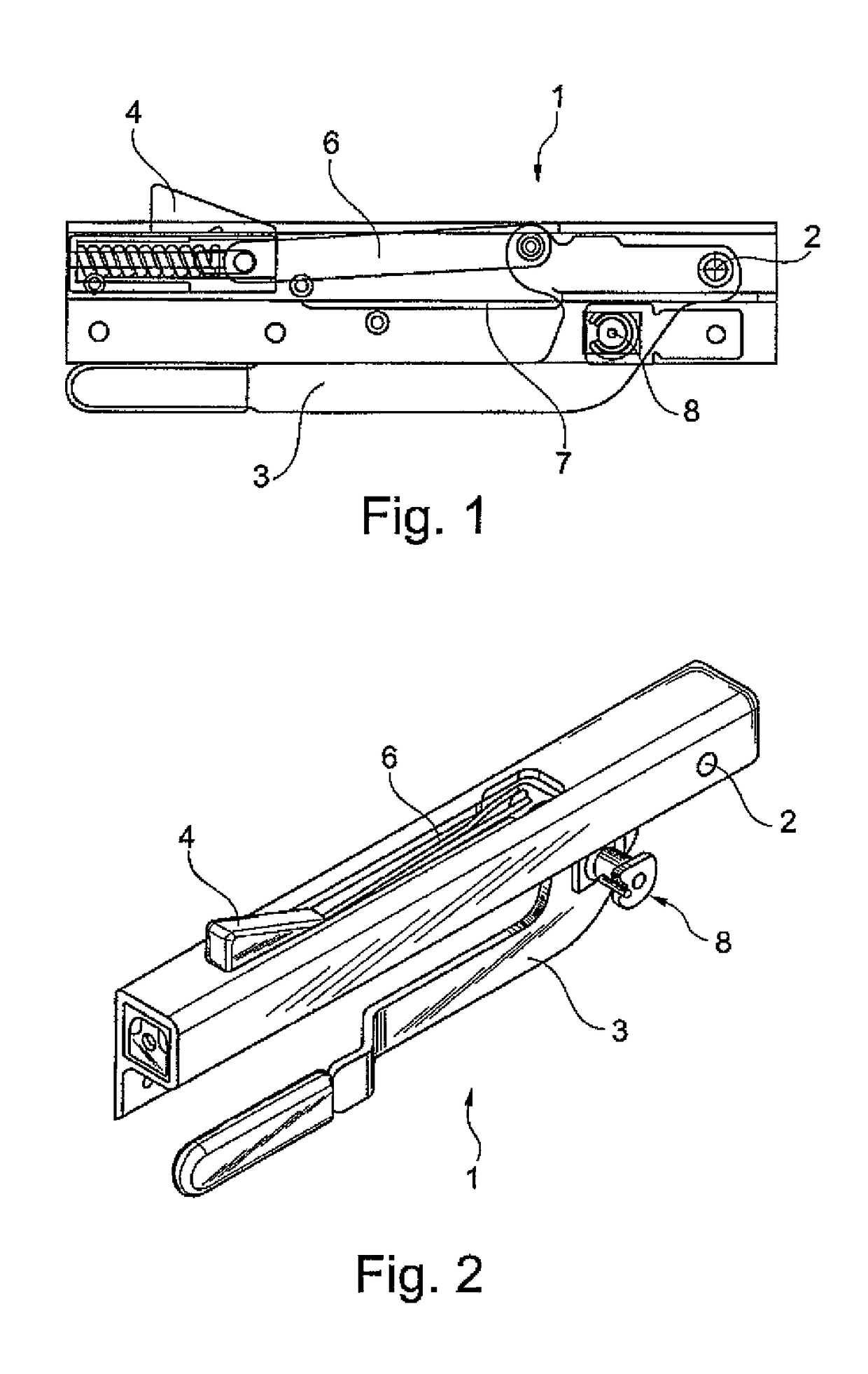
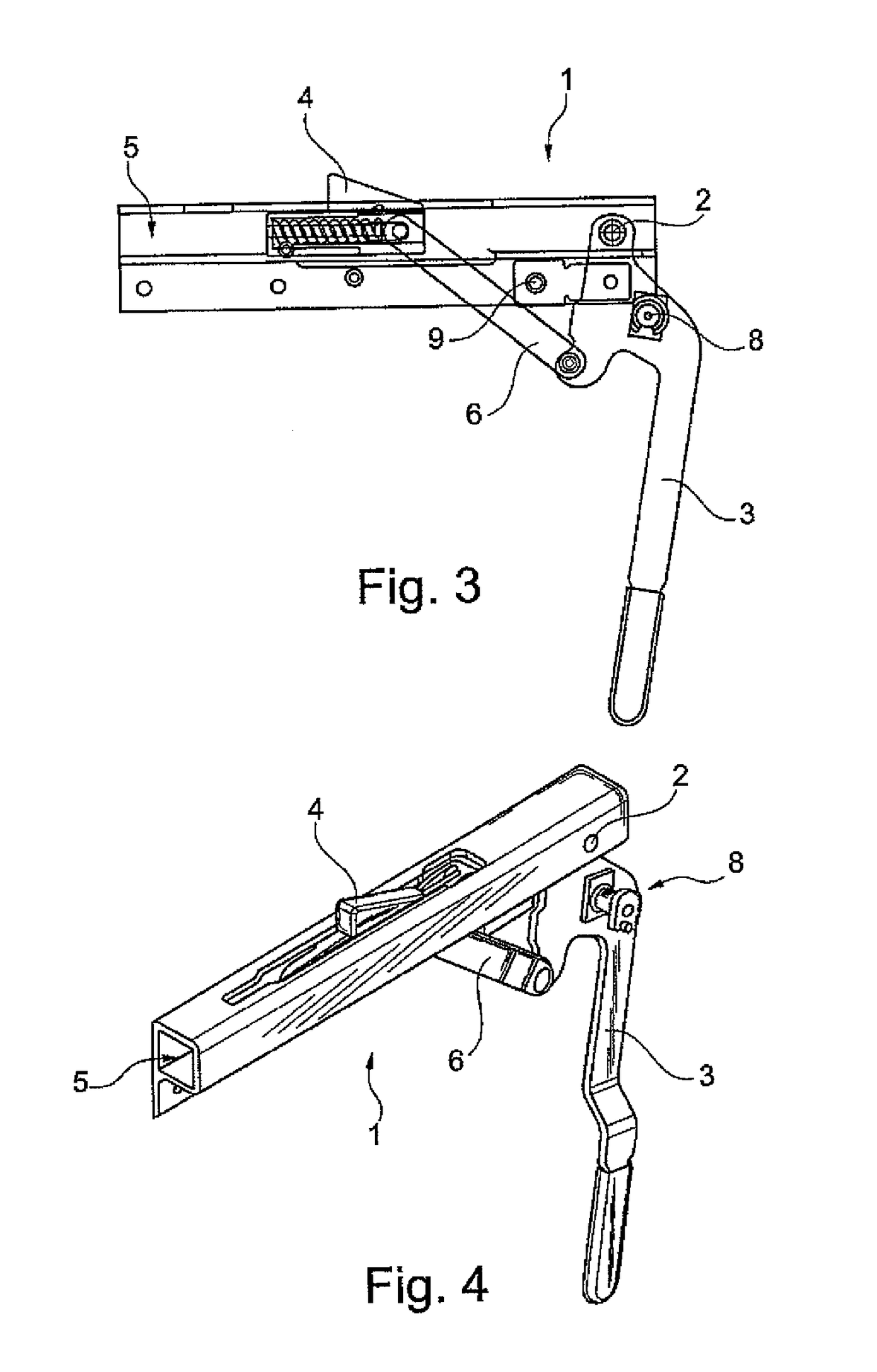
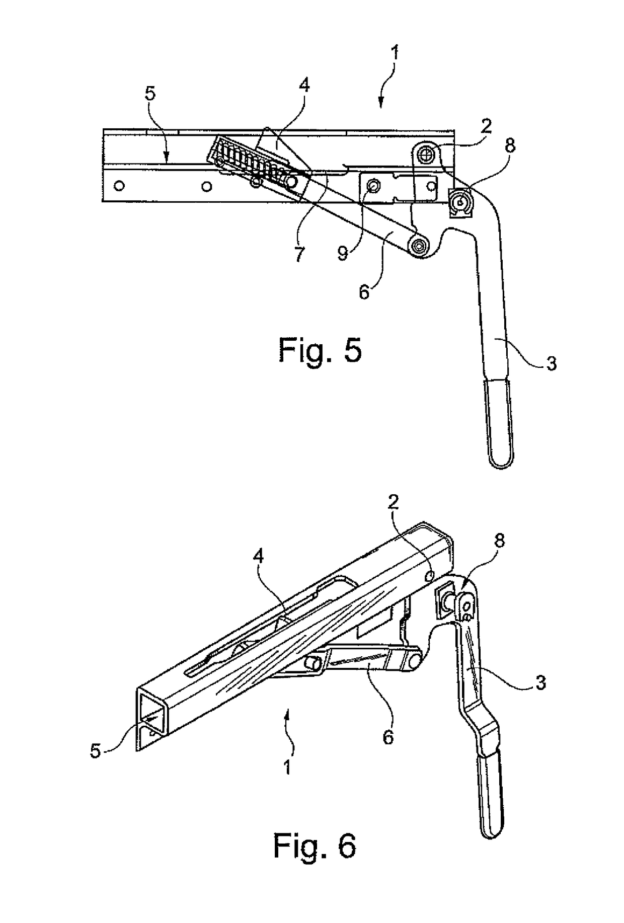
[0024]Matching reference characters are used in all the Figures for identical or similar components.

[0025]The Figures show a clamping device 1 for a sliding roof (not depicted in the drawings) that is displaceable along guidance and runner rails 15, clamping device 1 being provided in the region of the guidance and runner rail and comprising an actuation lever3 arranged pivotably about an axis 2 and shiftable between a locking position (FIGS. 1 and 2) and a release position (FIGS. 5 and 6), as well as a clamping element 4 modifiable in its position by means of actuation lever 3.

[0026]The clamping element 4 is arranged in a guide 5 aligned in accordance with the course of guidance and runner rail 15, and is shiftable in its guide 5 in a longitudinal direction, by way of a connecting element 6 attached in articulated fashion respectively to both the clamping element 4 and actuation lever 3, between a locking position (FIGS. 1 and 2) retaining an end carriage 10 (depicted in the drawi...


PUM


Abstract

A clamping device for sliding roofs is provided in the region of the guidance and runner rail. An actuation lever is pivotable between locking and release positions. A clamping element is modifiable in its position by means of the actuation lever, which coacts with a countermember of the end carriage and moves the end carriage to the end of the guidance and runner rail. The clamping element is aligned with the guidance and runner rail, and is shiftable in a longitudinal direction, between a locking position retaining the end carriage, and a release position. The guide comprises in a subregion on the underside an open space such that upon shifting of the actuation lever into the release position, the clamping element is at least partly lowerable sufficiently that the end carriage can be displaced away from the end of the guidance and runner rail.

Description

CROSS-REFERENCE TO RELATED APPLICATIONS AND CLAIM TO PRIORITY[0001]This application is related to application number 09011299.6-1268, filed Sep. 3, 2009, in the European Patent Office, the disclosure of which is incorporated herein by reference and to which priority is claimed.FIELD OF THE INVENTION[0002]The present invention relates to a clamping device for a sliding roof that is displaceable along a guidance and runner rail, the clamping device being provided in the region of the guidance and runner rail and comprising an actuation lever arranged pivotably about an axis and shiftable between a locking position and a release position, as well as a clamping element modifiable in its position by means of the actuation lever, which element coacts with a countermember provided on the end carriage and moves the end carriage to the end of the guidance and runner rail.BACKGROUND OF THE INVENTION[0003]Clamping devices that are arranged in the cargo space are known from practical use in a w...

Claims


Application Information

Patent Timeline
Patent Type & Authority Patents(United States)
IPC IPC(8): B60J7/185
CPCB60J5/065B60J7/185Y10T24/44017
Inventor WENSING, UDOHAHNEN, HANS BORISNEUMEYER, FRANKFRENTZEN, FRANKBIRKENBACH, ROLFROSSBACH, JOACHIMKEMMERLING, KARLSCHOLZ, AXELLAUTERBACH, TIMWEIGELT, ROLFANDERSSON, RAGNVALD
Owner VBG GROUP TRUCK EQUIP
Why Eureka
Try Eureka