Management of session control signaling for multicast/broadcast services

a multicast/broadcast and session control technology, applied in the direction of data switching networks, wireless commuication services, broadcast with distribution, etc., can solve the problems of unnecessary transmission of many session start messages, inflexible system, and considered rather stati

Inactive Publication Date: 2013-06-25
SOVEREIGN PEAK VENTURES LLC
View PDF10 Cites 14 Cited by
  • Summary
  • Abstract
  • Description
  • Claims
  • Application Information

AI Technical Summary

Benefits of technology

[0045]In view of the problems above, it is an object of the invention to suggest a mechanism for distributing session control signaling for a multicast or broadcast service within a mobile communications network that reduces the number of signaling connections. Another object is to design this mechanism to also allow for using it in providing a multicast or broadcast service in femto cells. A even further object of the invention is to suggest an authorization and / or transport type selection mechanism for authorizing Home NodeBs (i.e. user-controlled base station in contrast to operator-controlled base stations) and / or to select an appropriate transport mechanism for delivering the multicast or broadcast service within the femto cells.
[0048]Furthermore, another aspect of the invention is the distribution of session control signaling via a mobility management entity, which allows reducing the number of session control signaling connections that have to be terminated by the hierarchically higher network entities (e.g. the E-MBMS gateway towards the service network comprising the service provider, e.g. eBM-SC). In view of the potential need to provide the multicast or broadcast service within a certain sub-area of the entire service area irrespective of the number of users in this sub-area, it may be optionally foreseen that the session control signaling connections towards the service area parts that do not need to be constantly served are relayed via one or more mobility management entities, while the session control signaling connections towards the network portions in which the service is to be constantly provided are not relayed. Accordingly, depending on the desired availability of the service in different network parts / tracking areas, single-cell transmissions or multi-cell transmission may be used.
[0049]Considering the deployment of the multicast or broadcast service in femto cells, another aspect of the invention is that the delivery mechanism used for distribution of a multicast or broadcast service to a home base station (i.e. base stations not controlled by the network operator, such as for example a Home NodeB in 3GPP LTE) is decided depending on the location of the home base station with respect to the service area of the multicast or broadcast service. To decide on the delivery mechanism deciding core network entity may be provided with information on the home base station's location and / or a mobile terminal's (i.e. user's) location with respect to the macro cells in response to a service request of the mobile terminal requesting the service. By choosing the correct delivery mechanism, service continuity may be assured for the mobile terminal if it is moving out of the coverage area of femto cell controlled by the home base station.
[0097]In a further embodiment of the invention, the mobile terminal comprises a transmitter unit for transmitting a service request message for a multicast or broadcast service and for transmitting to the home base station controlling the femto cell, and a receiver unit for receiving in response to the service request message a authorization request message from the home agent triggering the mobile terminal to authorize the home base station. Furthermore, the mobile terminal is capable of transmitting an authorization request message to a network element of the core network of the mobile communication system. The transmitted authorization request message comprises a service identifier of the multicast or broadcast service and location information allowing the network element of the core network to determine whether the home base station is located in the service area of the requested multicast or broadcast service. Moreover, the mobile terminal may receive a response message to the authorization request message, wherein the response message is indicating whether the home base station is authorized to deliver the requested multicast or broadcast service or whether the mobile terminal is to request delivery via a dedicated bearer service at the source of the multicast or broadcast service.
[0102]Alternatively, in another embodiment the computer readable medium stores instructions that, when executed by the processor of a mobile terminal, cause the mobile terminal to transmit a service request message for a multicast or broadcast service and for transmitting to the home base station controlling the femto cell, receive in response to the service request message a authorization request message from the home agent triggering the mobile terminal to authorize the home base station, and transmit an authorization request message to a network element of the core network of the mobile communication system, wherein the authorization request message comprises a service identifier of the multicast or broadcast service and location information allowing the network element of the core network to determine whether the home base station is located in the service area of the requested multicast or broadcast service. The instructions further cause the mobile terminal to receive a response message to the authorization request message, wherein the response message is indicating whether the home base station is authorized to deliver the requested multicast or broadcast service or whether the mobile terminal is to request delivery via a dedicated bearer service at the source of the multicast or broadcast service.

Problems solved by technology

However, the MBSFN Areas typically cover only a small part of the entire MBMS Service Area.
But as there are most likely only few users present, this may lead to the unnecessary transmission of many Session Start messages to these eNBs.
Although the deployment may change over time, e.g. adding new cells to increase capacity, it can be considered rather static.
On the other hand, such a static approach results in an inflexible system, especially from a subscriber's point of view, as the user's perceived service quality depends on the operator's planning.
However, this system design may not be flexible enough to react on atypical situations, like the individual situation of the subscriber using the operator's network.
However, for an indoor location the signal strength may easily drop to 50% or less.
The base stations serving the pico cells are “normal” base stations from a functional point of view, but may have limited capabilities like processing power compared to conventional base stations serving the normal (or macro) cells.
Although technically possible, this changes the demands and requirements towards the mobile communications network.
Depending on the actual environment this may not be possible to be solved with network planning.
This may lead to connectivity problems, if many of them try to access the mobile communications network from their home at similar time.
However, in both options the operator risks inefficient utilization of the offered cell capacities during periods in which only few subscribers are located in the area, which is typically the case during daytime in such a scenario.
Generally, deployment of MBMS services to CSG cells may encounter similar problems as discussed above with respect to MBMS deployment to non-SFN network areas, in particular with respect to session control signaling.
Another potential problem to be considered in the MBMS deployment in CSG cells providing 3GPP access is security.
Another issue may be inefficient resource utilization for distribution of multicast or broadcast services to user located in CSG cells.

Method used


Image

  • Management of session control signaling for multicast/broadcast services
  • Management of session control signaling for multicast/broadcast services
  • Management of session control signaling for multicast/broadcast services

Examples


Embodiment Construction

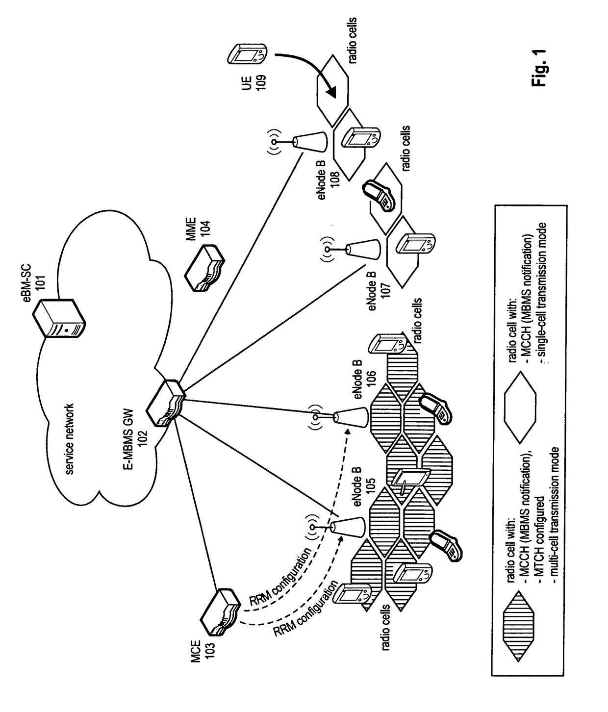
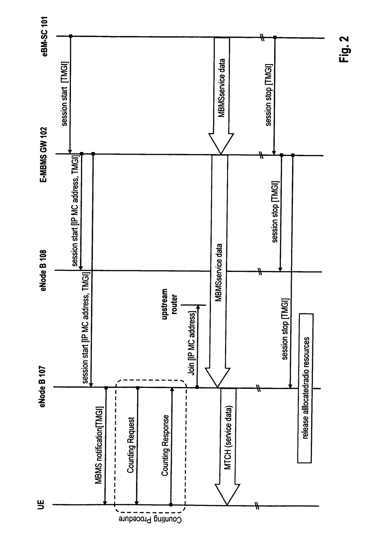
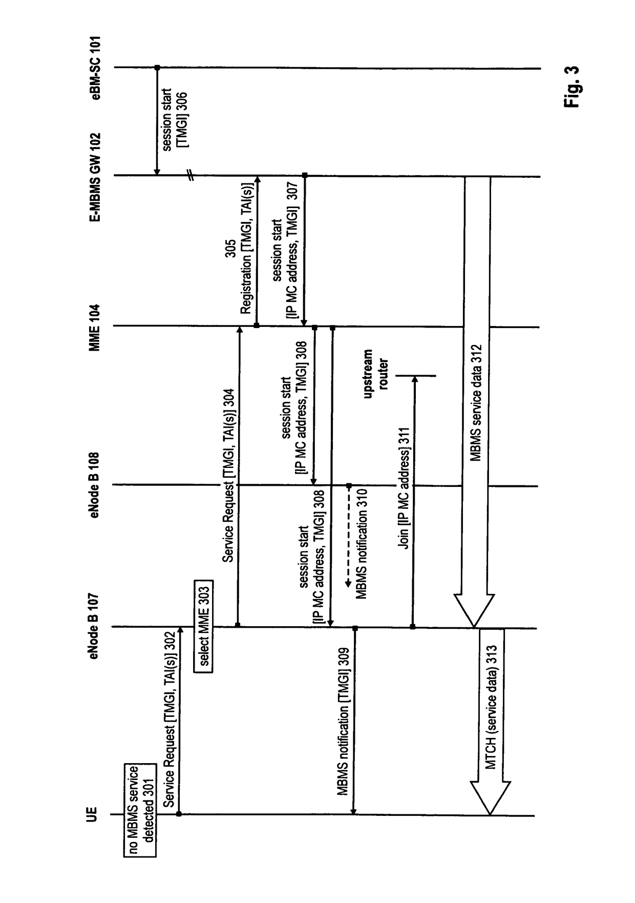
[0115]The following paragraphs will describe various embodiments of the invention. For exemplary purposes only, most of the embodiments are outlined in relation to an (evolved) UMTS communication system according to SAE / LTE discussed in the Technical Background section above. It should be noted that the invention may be advantageously used for example in connection with a mobile communication system such SAE / LTE communication system, but the invention is not limited to its use in this particular exemplary communication network.

[0116]The explanations given in the Technical Background section above are intended to better understand the mostly SAE / LTE specific exemplary embodiments described herein and should not be understood as limiting the invention to the described specific implementations of processes and functions in the mobile communication network. Nevertheless, it should be noted the improvements proposed herein may be readily applied in the architecture / system described in th...


PUM


Abstract

The invention relates to a method for distributing control signaling for session control of a multicast or broadcast service within a mobile communication network. Furthermore the invention also provides a base station, mobile terminal and communication system to perform the proposed method. In order to reduce the number of signaling connections for the service, the invention proposes to avoid the initial distribution of session control signaling in the entire mobile communications network or service area. Rather than providing service related control signaling connections upon session start, the control signaling connections are set up in response to service requests of the mobile terminals requesting the service. According to one further aspect, the mobile terminals send the service requests based on service announcements available at the mobile terminals, i.e. in contrast to conventional implementations, the mobile terminals do not await a notification of the access network on the availability of the service within the cell.

Description

FIELD OF THE INVENTION[0001]The invention relates to a method for distributing control signaling for session control of a multicast or broadcast service within a mobile communication network. Furthermore the invention also provides a base station, mobile terminal and communication system to perform the proposed method.TECHNICAL BACKGROUND3GPP Long Term Evolution (LTE) & MBMS for LTE[0002]An architecture for Multicast / Broadcast Services (MBMS) is discussed as part of the LTE / SAE standardization within 3GPP (SAE=System Access Evolution). In order to distinguish this evolved service architecture from previous architecture releases it is sometimes also referred to as E-MBMS. Similarly, in order to distinguish from the conventional UMTS Terrestrial Radio Access Network (UTRAN), the LTE network is also referred to as E-UTRAN.[0003]Generally an E-MBMS service might be available in a certain area, which is usually referred to as the MBMS Service Area. This service area might span the entire...

Claims


Application Information

Patent Timeline
Patent Type & Authority Patents(United States)
IPC IPC(8): H04W4/00
CPCH04W72/005H04W72/30
Inventor BECKER, RALFGONSA, OSVALDOFUKUI, AKITOKANAZAWA, TAKESHI
Owner SOVEREIGN PEAK VENTURES LLC
Why Eureka
Try Eureka