Trench shower drain

a drain and shower technology, applied in sewer pipelines, metal working devices, manufacturing tools, etc., can solve the problems of tile setter virtually impossible situation, leakage problems at intersections, and tile base setting problems, so as to reduce inventory costs and tooling investment.

Active Publication Date: 2013-07-02
NOBLE CO LTD
View PDF38 Cites 61 Cited by
  • Summary
  • Abstract
  • Description
  • Claims
  • Application Information

AI Technical Summary

Benefits of technology

[0014]The present system has several advantages including: very waterproof (especially given a lack of welds on metal drain components), foolproof in terms of installation, cost effective given the few and simple components, mates well with existing shower drain systems. The trench body made by a formed plastic block is seen as a real advantage given the low volume of these parts, since it can be manufactured on a just-in-time basis (which minimizes inventory cost and tooling investment), such as by being machined with CNC equipment.

Problems solved by technology

However, these configurations cause problems as noted below.
Each sector of these polygons creates an intersecting plane that creates problems for the setting of tile on the base.
Even with small tile or stone (2″×2″), these changes in plane make the finished floor show these changes in plane, which can be aesthetically unacceptable and further can lead to leak problems at lines of intersection.
With the design world trending to larger format tile, the setting of tile with intersecting planes creates a virtually impossible situation for the tile setter due the changes in plane.
This creates a problem for the installation since all drains are designed to be parallel to the subfloor.
Since the vast majority of applications are over occupied space, the watertight integrity of the drain system is critical and flood testing is required by most plumbing codes.
Due to the large number of sizes required by the design community, the ability to build multiple size dies for the drain bodies is not cost effective.
However, welding is expensive and can lead to leak problems.
For example, many times welding is the cause for small undetectable leaks that lead to water problems in the field that will not be noticed for many years, at a time when they have already created considerable problems such as rotted under-floor structures and smells associated with wet moldy environments.
Notably, leaks can occur at the welds either at the time of manufacture, or during or after installation.
These leaks can increase over time (or show up for a first time), due to corrosion and / or stress during installation and / or fatigue and / or from material stress caused in part by the welding.
Quality control of welding is difficult, time consuming, and can add considerably to manufacturing expense, particularly where the welding extends 360 degrees around a pipe or connection.
It is noted that shower trench drains are unforgiving, in that the water being drained away will find all leaks, and will eventually cause a problem.
Additionally, most known shower trench drains have trench bodies that are made of sheet metal formed with multi-angled surfaces, making them difficult to accurately position during an installation.
This factor leads to difficult installations since the drain body needs to be supported by dry packed mortar (or adjustable jacks that are left in the mortar bed) at a perfect sloped angle.
It is not easy to form dry packed mortar at a perfect sloped angle, as required to support the known shower trench drain bodies.
Molded trench drains also have a similar problem.
Specifically, trench drains that are molded from thermoplastic materials effectively have the same issues since constant-thickness wall design is a typical requirement for injected molded designs.
Whether the drain is made from metal or plastic material, the costs to tool the numerous sizes is often cost prohibitive.
Complex configurations other than straight are generally too complex to fabricate in metal, except by welding as noted above, since their low volume manufacture makes it cost prohibitive to invest in expensive capital-intensive tooling.

Method used


Image

  • Trench shower drain
  • Trench shower drain
  • Trench shower drain

Examples


Embodiment Construction

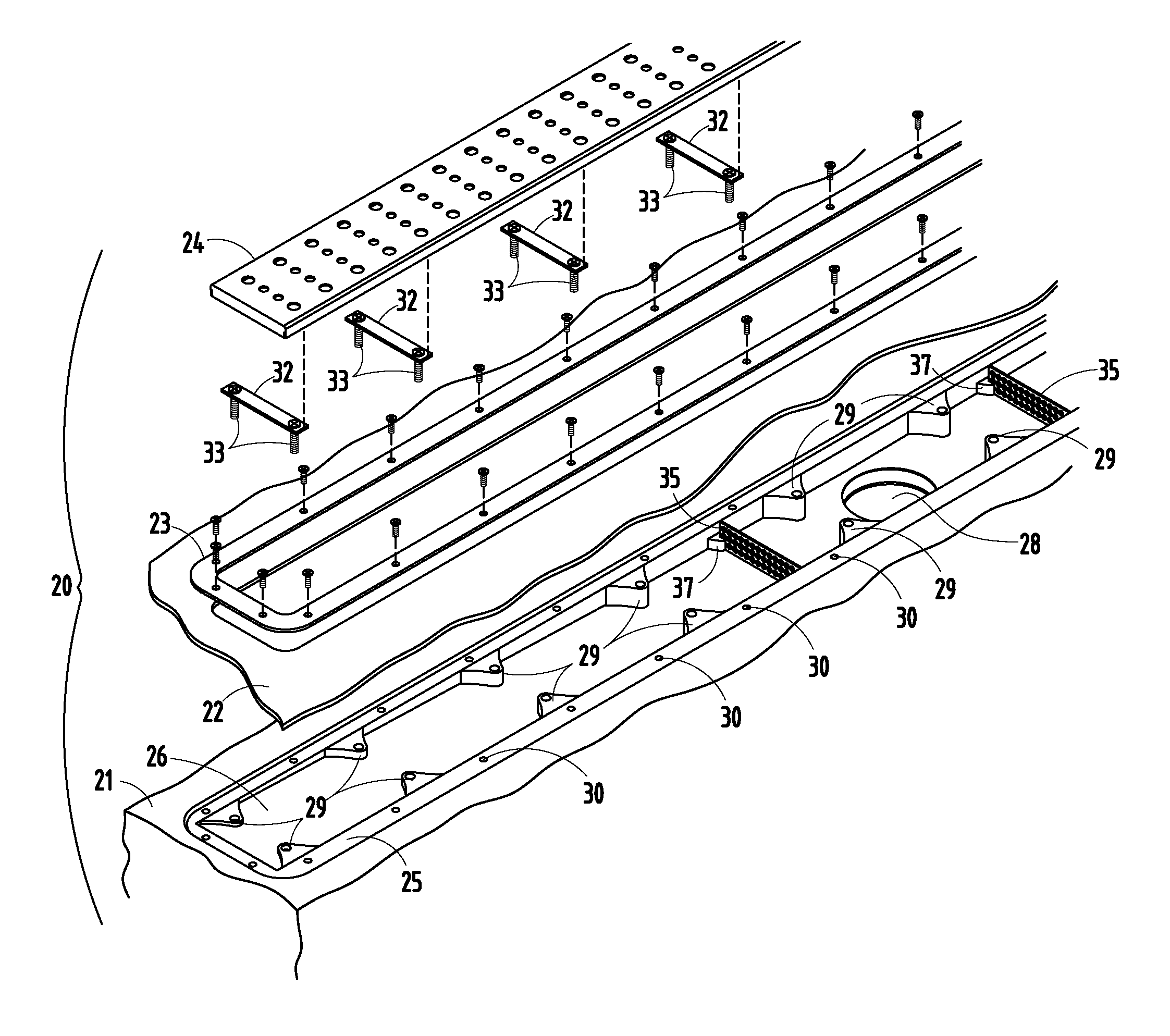
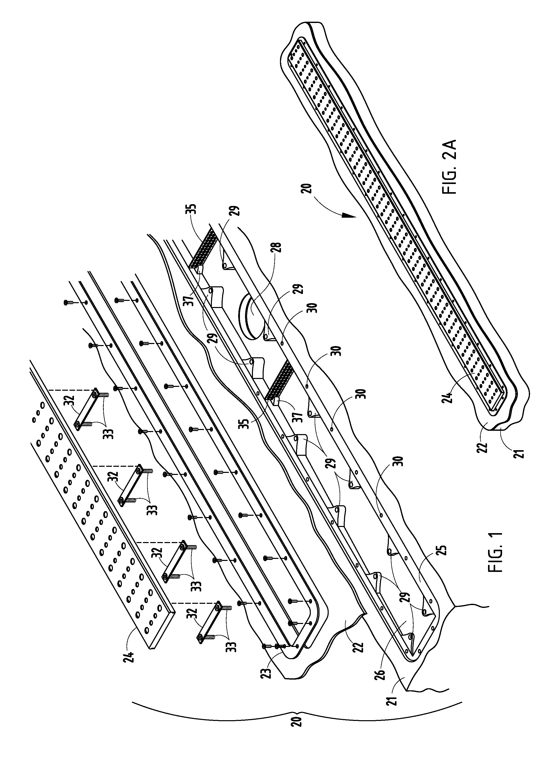
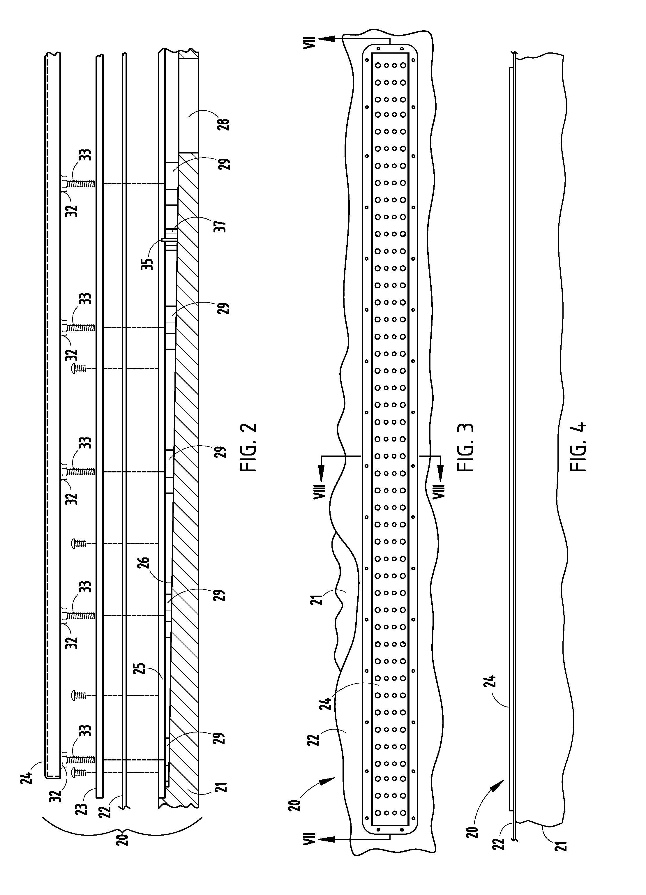
[0020]The present shower trench drain apparatus includes a trench body constructed from a single block of material machined to its final shape including various integral features. It is contemplated that the material will typically be selected to be a polymer such as PVC (Poly Vinyl Chloride) or ABS (Acrylonitrile butadiene styrene). A reason is because these materials are capable of being machined in addition to being compatible with common types of rigid pipe used in the plumbing industry. Further, it is noted that PVC and ABS materials are widely available in large format sheets with many available thicknesses. This allows the construction of complex design shapes by CNC machining with the only limitation being the overall dimension of the raw block. The present inventive concepts are based in part on the premise that it is far more cost effective (for manufacturing, installation, and durability reasons) to design and manufacture configurations into a block of material than it is...


PUM

PropertyMeasurementUnit
straight lengthaaaaaaaaaa
widthaaaaaaaaaa
lengthaaaaaaaaaa

Abstract

A shower trench drain apparatus includes a shower trench drain body of polymeric material having an integrally-formed drain channel with angled bottom surface and drain opening or openings, a waterproof membrane over the drain body, a clamp ring retaining the membrane to the drain body, and a grate adjustably retained to the drain body by a height adjustment mechanism. The trench drain body formed from a block of material such as PVC or ABS, which are compatible with approved plumbing materials and codes. The block has a flat bottom adapted for horizontal support during installation and includes integrally-formed features facilitating adjustment during installation while minimizing components and separate parts and simplicity of installation.

Description

BACKGROUND[0001]The present invention relates to shower drains, such as are often used in residential, commercial, and institutional shower constructions.[0002]Typical tiled showers must by code and design have a slope that moves the water from all floor surfaces to the drain. A normal shower configuration would be a square, rectangle, or a polygon. Those configurations mandate four or more triangular shaped quadrants all converging at the drain. Modern day designs have mandated larger overall size showers and more complex base configurations. The larger the shower foot print, the longer the slope. However, these configurations cause problems as noted below.[0003]Each sector of these polygons creates an intersecting plane that creates problems for the setting of tile on the base. Even with small tile or stone (2″×2″), these changes in plane make the finished floor show these changes in plane, which can be aesthetically unacceptable and further can lead to leak problems at lines of i...

Claims


Application Information

Patent Timeline
Patent Type & Authority Patents(United States)
IPC IPC(8): A47K3/00
CPCE03F3/046E03F5/0408E03F5/0409Y10T29/49826E03F2005/0413Y02A30/60
Inventor KIK, SR., PAUL S.KIK, JR., PAUL S.
Owner NOBLE CO LTD
Why Eureka
Try Eureka