Lockable ejector device for a furniture part movably supported in piece of furniture

a technology of ejector device and furniture part, which is applied in the direction of furniture parts, wing fasteners, domestic applications, etc., can solve the problems of inclination of the front panel, disadvantage of additional space required in respect of the depth of the furniture piece, etc., and achieves the effect of easy adjustment of the front gap and positive influence on the stability and service life of the devi

Active Publication Date: 2013-07-02
JULIUS BLUM GMBH
View PDF30 Cites 11 Cited by
  • Summary
  • Abstract
  • Description
  • Claims
  • Application Information

AI Technical Summary

Benefits of technology

[0016]In that respect a structurally simple solution is provided if at least one locking unit includes a slide portion which is supported linearly movably with respect to a base portion and on which the receiving element is arranged, wherein the displacement device for altering the relative position of the receiving element is of such a configuration and arrangement that it acts directly on the slide portion. In other words the fitter or the user can easily adjust the front gap without using a tool by turning the actuating element.
[0017]If at least one locking unit has a blocking mechanism for releasably fixing the preferably rotatably supported receiving element in a position of arresting the engagement element and if locking of the ejector device is effected by means of the blocking mechanism for the receiving element that overall provides a particularly compact solution involving few components, which obviously has a positive influence on the stability and the service life of the device according to the invention.
[0018]To avoid damage which can occur in the event of improper operation by a user, a further embodiment of the invention provides that at least one locking unit has an overload safety mechanism which includes at least two parts which are movably connected together and which allows damage-free opening of the movable furniture part even when the receiving element is fixed by means of the blocking mechanism in a position of arresting the engagement element.

Problems solved by technology

In that case the additional space required in respect of the depth of the article of furniture has been found to be a disadvantage.
In addition, coupling of the two locking units by means of the torsion bar involves a tendency for the front panel to assume an inclined position.

Method used


Image

  • Lockable ejector device for a furniture part movably supported in piece of furniture
  • Lockable ejector device for a furniture part movably supported in piece of furniture
  • Lockable ejector device for a furniture part movably supported in piece of furniture

Examples


Embodiment Construction

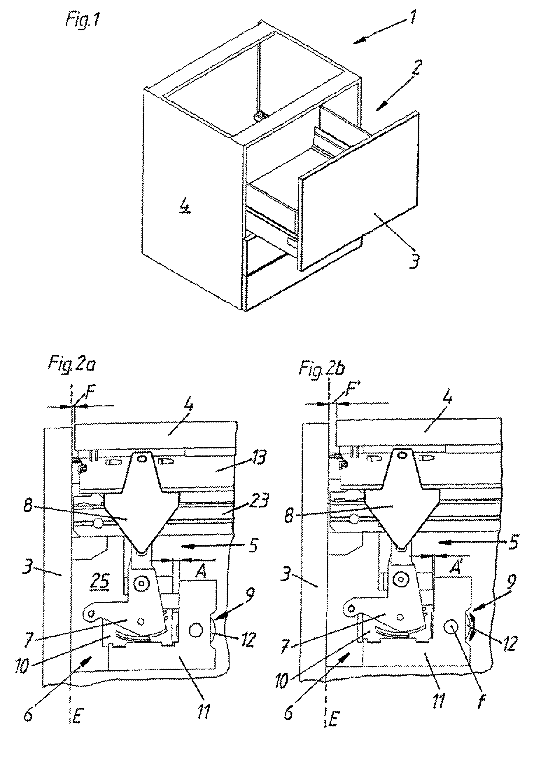
[0056]FIG. 1 quite generally shows an article of furniture 1 having a furniture part 2 supported movably therein. In this case opening of the movable furniture part 2 formed by a drawer is effected by way of a touch-latch mechanism, that is to say the user pushes the movable furniture part 2 from a closed end position E in the closing direction SR of the movable furniture part 2 further into the article of furniture 1 by a predetermined distance by applying force to the handle-less front panel 3, whereby locking of an ejector device is released and the movable furniture part 2 is extended into an open position out of the article of furniture 1 by means of the ejector device.

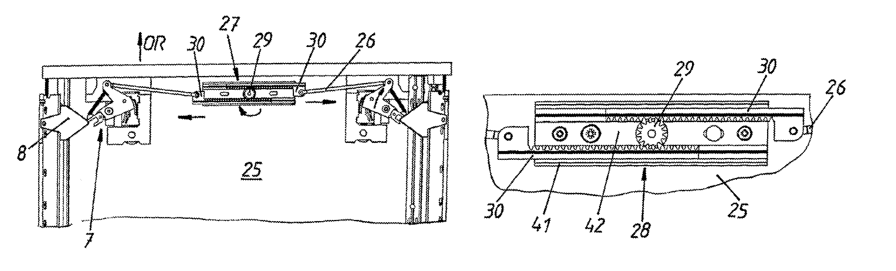
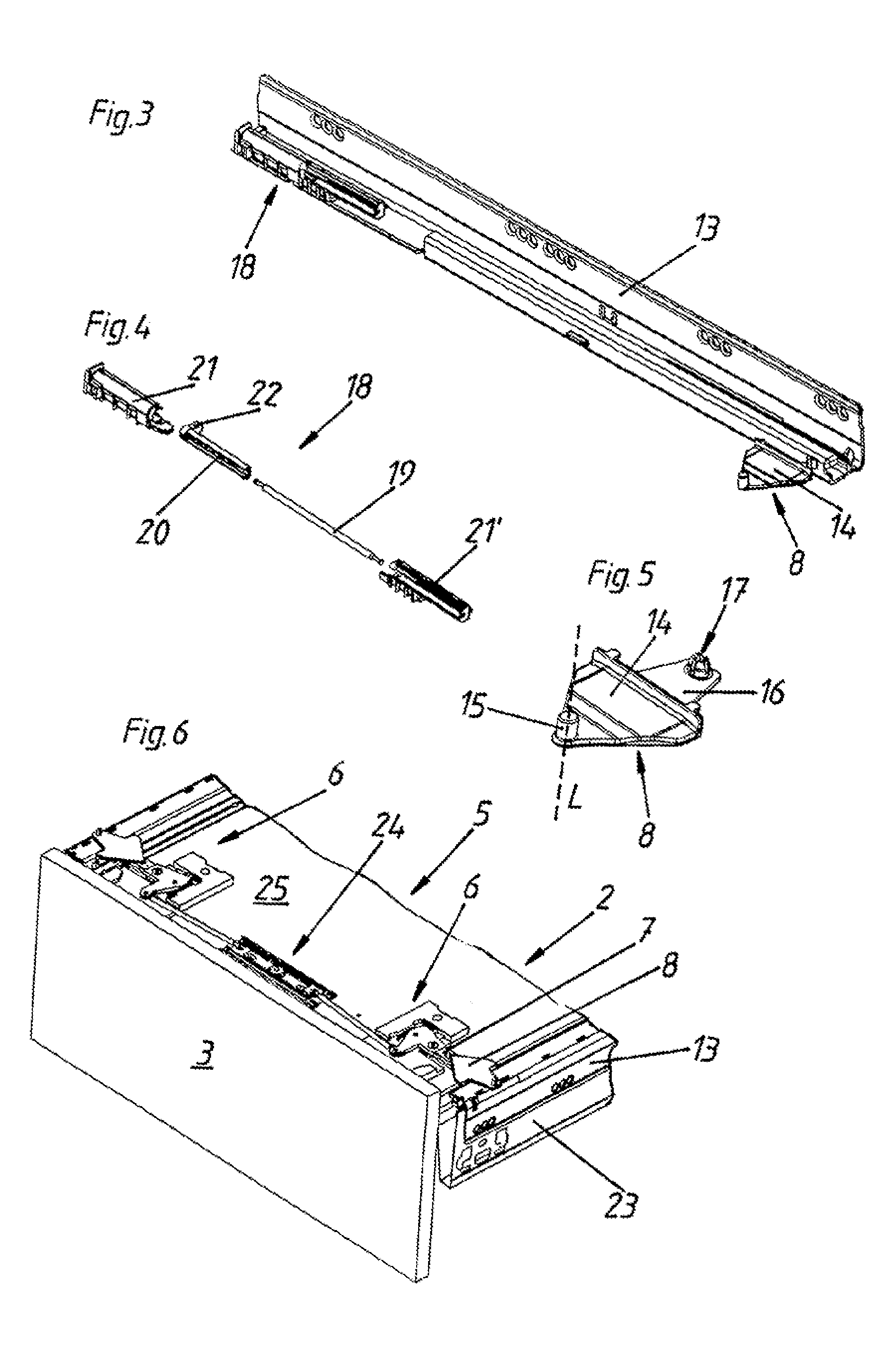
[0057]FIGS. 2a and 2b show a portion of a view from below of a furniture part 2 supported movably in an article of furniture 1. In this case the movable furniture part 2 is movably guided by means of a drawer rail 23 in a carcass rail 13 stationarily arranged on the body or carcass 4 of the article of furniture 1...


PUM


Abstract

The invention relates to a lockable ejector device for a furniture part that is movably supported in a piece of furniture, including a fixing device for locking the movable furniture part in place in a closed end position, and at least one ejector element for moving the movable furniture part from the closed end position into an open position, wherein the fixing device comprises at least two locking units, which are coupled to each other and each have a receiving element for an engagement element. The at least two locking units are operatively connected to each other by way of a synchronization mechanism, which has at least two coupling elements, each associated with different locking units, and at least one synchronization unit. The coupling elements are coupled by way of the synchronization unit with respect to the movements thereof.

Description

[0001]This application is a Continuation of International application PCT / AT2009 / 000101, filed Mar. 13, 2009.BACKGROUND OF THE INVENTION[0002](1) Field of the Invention[0003]The invention concerns a lockable ejector device for a furniture part movably supported in an article of furniture, comprising an immobilization device for arresting the movable furniture part in a closed end position and at least one ejector element for moving the movable furniture part out of the closed end position into an open position, wherein the immobilization device has at least two locking units which are coupled together and each have a respective receiving element for a respective engagement element.[0004](2) Description of Related Art[0005]Such a device is known for example from Austrian utility model AT 8882 U1. In the device shown therein the two locking units are arranged at the rear end of the drawer and are coupled together by way of a torsion bar. In that case the additional space required in r...

Claims


Application Information

Patent Timeline
Patent Type & Authority Patents(United States)
IPC IPC(8): A47B95/00A47B88/00
CPCA47B88/0477E05C19/022E05B65/46A47B88/463
Inventor KOENIG, BERNDDURING, MARTIN
Owner JULIUS BLUM GMBH
Why Eureka
Try Eureka