Vehicle side airbag apparatus

a technology for side airbags and apparatuses, which is applied in the direction of vehicular safety arrangments, vehicle components, pedestrian/occupant safety arrangements, etc., can solve the problems of complicated structure of apparatuses, and achieve the effects of easy sewing, excellent effect and easy manufacturing

Active Publication Date: 2013-07-09
TOYOTA JIDOSHA KK
View PDF14 Cites 13 Cited by
  • Summary
  • Abstract
  • Description
  • Claims
  • Application Information

AI Technical Summary

Benefits of technology

[0008]It is an object of the invention to provide a vehicle side airbag that may be easily adapted to fit in various vehicle models with only slight adjustments in dimensions, thereby substantially reducing costs. The side vehicle airbag according to the invention has a simple structure, and is capable of restraining a rear portion of a passenger in the event of a lateral collision.

Problems solved by technology

However, in each of the conventional examples, the side airbag apparatus has a complicated structure, and the complicated structure needs to be customized to appropriately fit different vehicle models.

Method used


Image

  • Vehicle side airbag apparatus
  • Vehicle side airbag apparatus
  • Vehicle side airbag apparatus

Examples


first embodiment

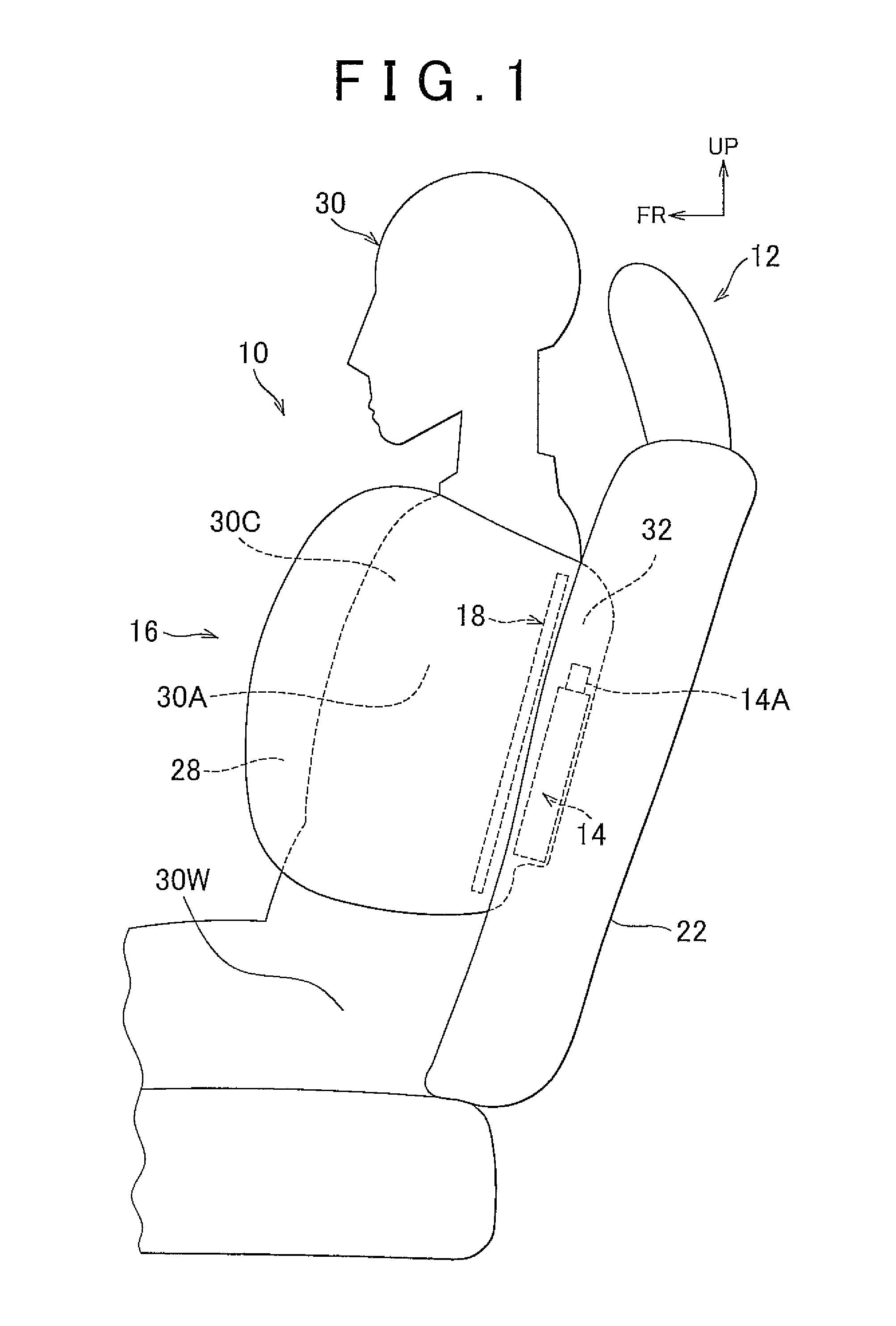
[0031]In FIG. 1, a vehicle side airbag apparatus 10 according to the invention may be mounted on, for example, a vehicular seat 12, and includes an inflator 14, a side airbag 16, and a tether 18.

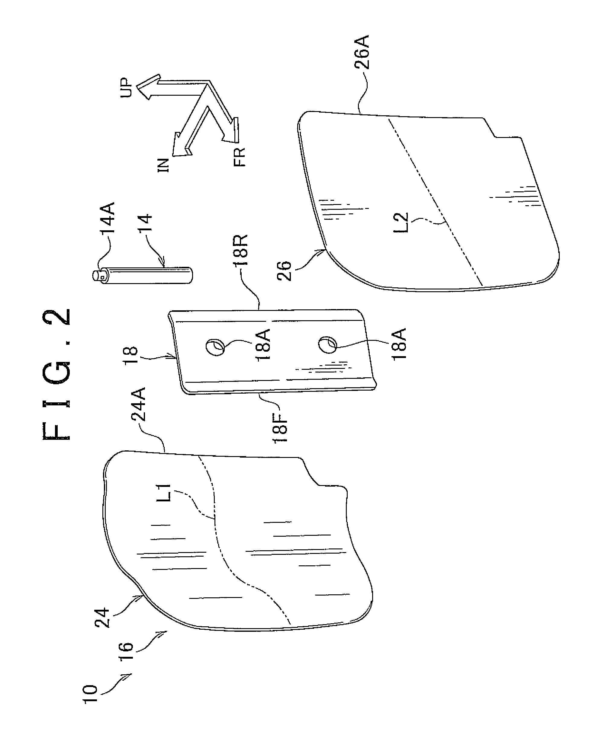
[0032]In FIGS. 1 and 2, the inflator 14 is a tubular gas generation source that discharges a gas when a lateral collision occurs. The inflator 14 is provided in a rear chamber 32, which will be described later, with a gas discharge port 14A directed upward. Alternatively, the inflator 14 may be arranged with the gas discharge port 14A being directed downward.

[0033]The inflator 14 is connected to an airbag ECU (not shown). The airbag ECU directs a working current to flow to the inflator 14 when the occurrence of a lateral collision is detected from a signal from a lateral collision sensor (not shown) or predicted. “The event of a lateral collision” can include the prediction of a lateral collision as well as the actual occurrence of a lateral collision. The event of the prediction of a latera...

second embodiment

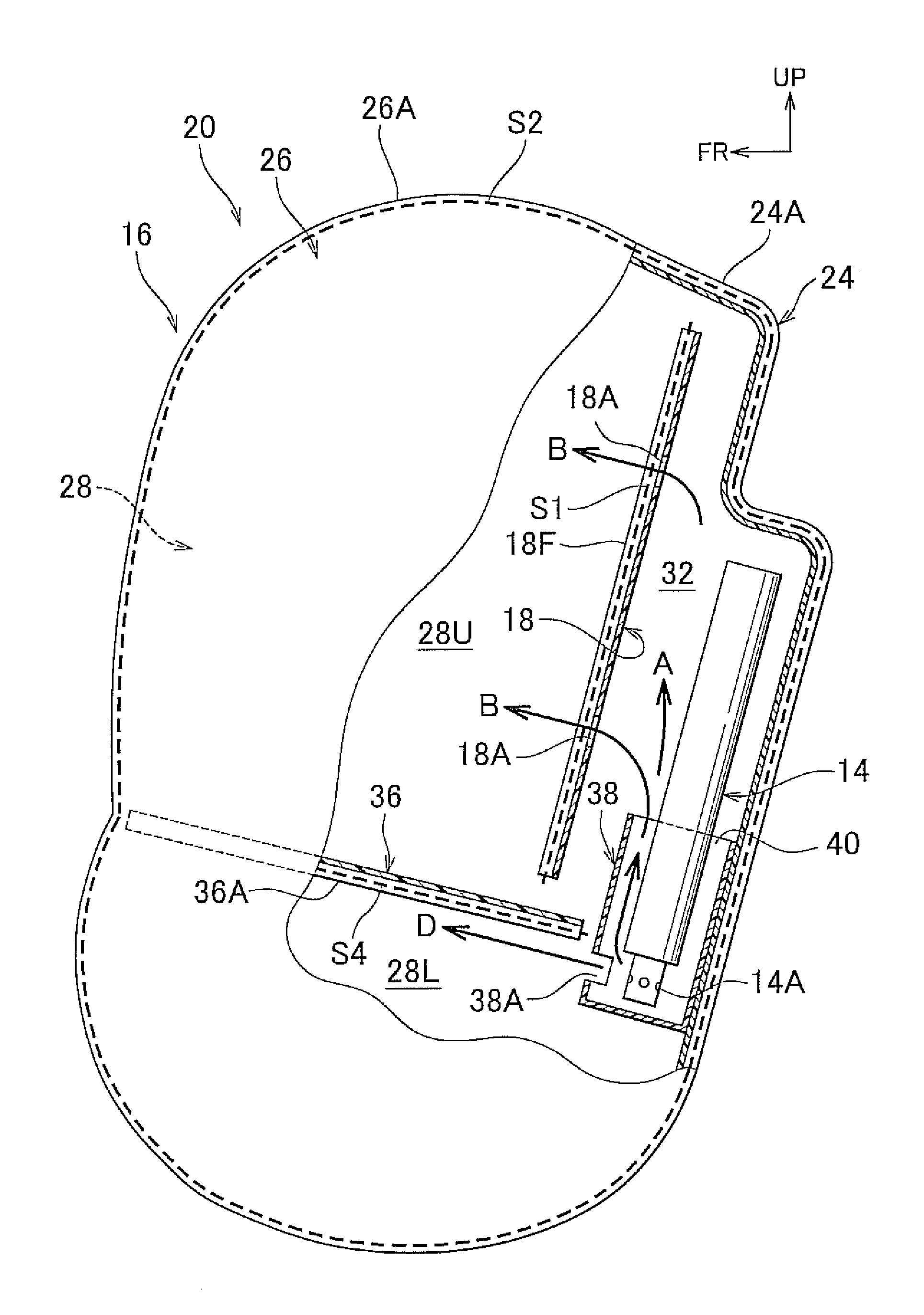
[0049]In FIG. 6, in a vehicle side airbag apparatus 20 according to the invention, the main chamber 28 has an upper chamber 28U corresponding to the chest portion 30C (see FIG. 1) of the passenger 30, and a lower chamber 28L corresponding to a waist portion 30W (see FIG. 1) of the passenger 30. The tether 18 partitions the rear chamber 32 and the upper chamber 28U from each other.

[0050]The main chamber 28 is provided with a partition wall 36 that partitions the upper chamber 28U and the lower chamber 28L from each other and suppresses the bag thickness of a boundary portion between the upper chamber 28U and the lower chamber 28L during expansion. The partition wall 36 uses a non-elastic base fabric similar to the passenger-side base fabric 24 and the vehicle body-side base fabric 26. Further, the partition wall 36 extends in, for example, a range from a front end of the side airbag 16 to a front side of the inflator 14 located in the rear chamber 32. The width of the partition wall ...


PUM


Abstract

A vehicle side airbag apparatus has an inflator that discharges gas when a lateral collision occurs, a side airbag that is formed by sewing a passenger-side base fabric to a vehicle body-side base fabric, that is folded when it is stored and is inflated when gas is supplied from the inflator to be deployed into a space between a passenger seated in a vehicular seat and a vehicle body side portion, and a tether that couples a middle region of the passenger-side base fabric in a longitudinal direction of a vehicle with either a rear region of the passenger-side base fabric or the vehicle body-side base fabric in the longitudinal direction of the vehicle, and partitions the side airbag into a main chamber, which comes into contact with a lateral portion of the passenger, and a rear chamber, which comes into contact with a rear portion of the passenger, during deployment.

Description

INCORPORATION BY REFERENCE[0001]The disclosure of Japanese Patent Application No. 2011-022905 filed on Feb. 4, 2011 including the specification, drawings and abstract is incorporated herein by reference in its entirety.BACKGROUND OF THE INVENTION[0002]1. Field of the Invention[0003]The invention relates to a vehicle side airbag apparatus.[0004]2. Description of Related Art[0005]In the light of a characteristic indicating that a rear portion of the passenger is hardier than a front portion of the passenger, a side airbag apparatus that protects a passenger is described in Japanese Patent Application Publication No. 2008-201175 (JP-A-2008-201175). The side airbag apparatus is composed of an inner bag that covers, in the longitudinal direction of a vehicle, a range from the back of the passenger to the middle of the passenger's chest in a standard body shape, and an outer bag that covers a range from the back of the passenger to the front of the passenger's abdomen.[0006]Furthermore, i...

Claims


Application Information

Patent Timeline
Patent Type & Authority Patents(United States)
IPC IPC(8): B60R21/231
CPCB60R21/23138B60R2021/23146B60R2021/23382
Inventor FUKAWATASE, OSAMUFUJIWARA, YUSUKE
Owner TOYOTA JIDOSHA KK
Why Eureka
Try Eureka