
Hierarchical bloom filters for facilitating concurrency control

a concurrency control and hierarchy filter technology, applied in computing, instruments, electric digital data processing, etc., can solve the problems of limiting application performance, synchronization overhead becoming the dominant factor in limiting application performance, and the process of acquiring a lock and releasing a lock can be very time-consuming in modern microprocessors, so as to facilitate concurrency control

Active Publication Date: 2013-07-09
ORACLE INT CORP
View PDF5 Cites 30 Cited by
  • Summary
  • Abstract
  • Description
  • Claims
  • Application Information

AI Technical Summary

Benefits of technology

The described embodiments are about a system that helps control what parts of a computer system can access memory at the same time. It does this by creating special data structures called signatures, which are used to detect if two parts of the system might interfere with each other. If a potential conflict is detected, the system manages the execution of the two parts of the system so they don't interfere with each other. This helps make the computer system run more efficiently and concurrently.

Problems solved by technology

However, as microprocessor performance continues to increase, the time spent synchronizing between threads (processes) is becoming a large fraction of overall execution time.
In fact, as multi-threaded applications begin to use even more threads, this synchronization overhead often becomes the dominant factor in limiting application performance.
Unfortunately, the process of acquiring a lock and the process of releasing a lock can be very time-consuming in modern microprocessors.
They typically involve atomic operations, which flush load and store buffers, and can consequently require hundreds, if not thousands, of processor cycles to complete.
However, a Bloom filter may produce false positives, and such false positives may increase in frequency as elements are added to the Bloom filter.
Consequently, conflict detection using Bloom filters may become unwieldy or inaccurate as read and write set signatures grow in size and complexity.

Method used


Image

  • Hierarchical bloom filters for facilitating concurrency control
  • Hierarchical bloom filters for facilitating concurrency control
  • Hierarchical bloom filters for facilitating concurrency control

Examples


Embodiment Construction

[0030]The following description is presented to enable any person skilled in the art to make and use the embodiments, and is provided in the context of a particular application and its requirements. Various modifications to the disclosed embodiments will be readily apparent to those skilled in the art, and the general principles defined herein may be applied to other embodiments and applications without departing from the spirit and scope of the present disclosure. Thus, the present invention is not limited to the embodiments shown, but is to be accorded the widest scope consistent with the principles and features disclosed herein.

[0031]The data structures and code described in this detailed description are typically stored on a computer-readable storage medium, which may be any device or medium that can store code and / or data for use by a computer system. The computer-readable storage medium includes, but is not limited to, volatile memory, non-volatile memory, magnetic and optical...


PUM


Abstract

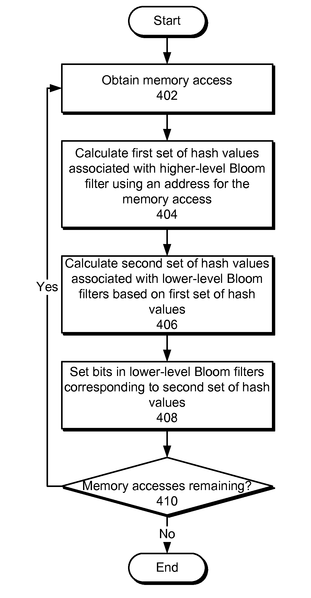
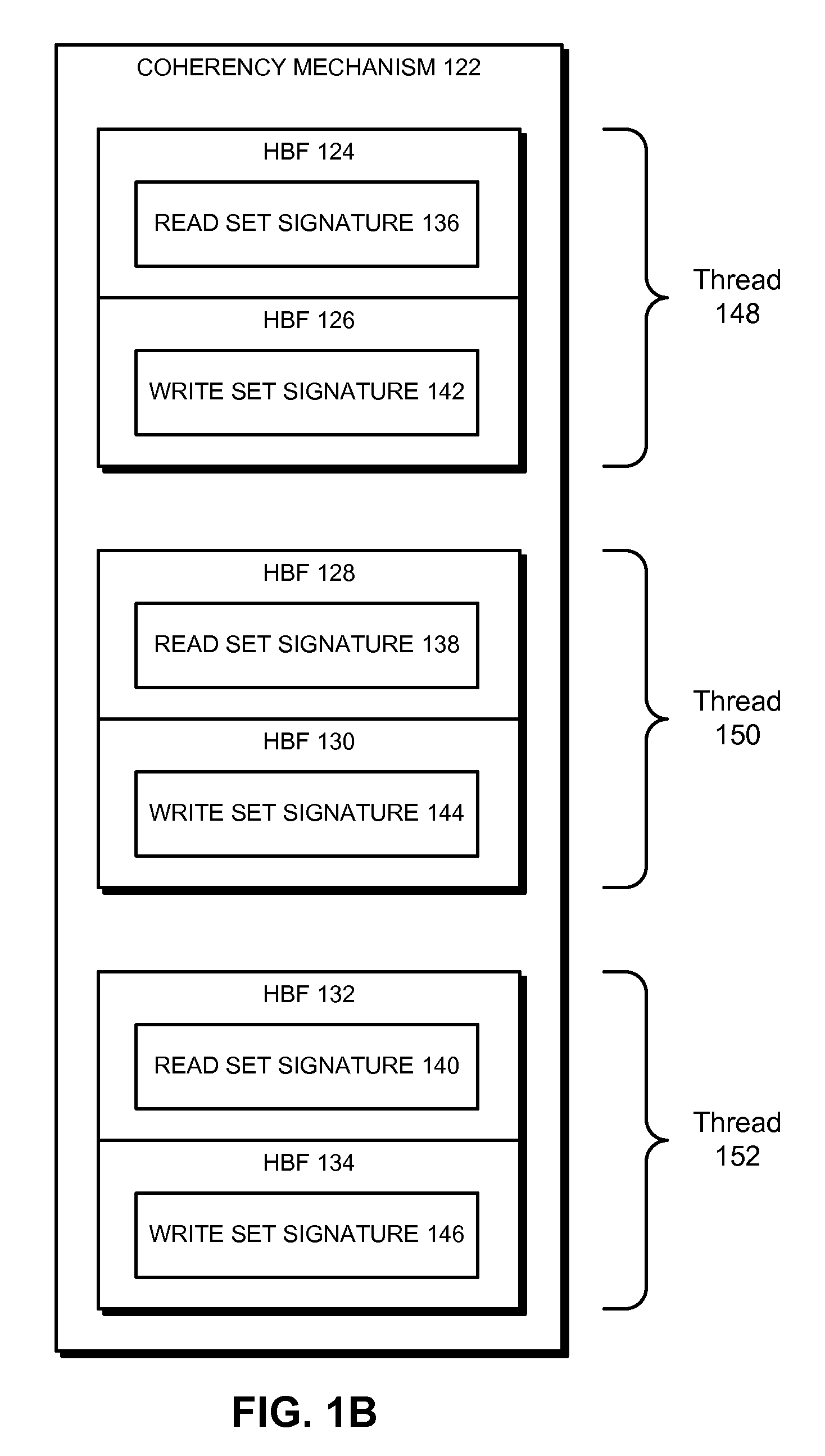
Some embodiments provide a system that facilitates concurrency control in a computer system. During operation, the system generates a set of signatures associated with memory accesses in the computer system. To generate the signatures, the system creates a set of hierarchical Bloom filters (HBFs) corresponding to the signatures, and populates the HBFs using addresses associated with the memory accesses. Next, the system compares the HBFs to detect a potential conflict associated with the memory accesses. Finally, the system manages concurrent execution in the computer system based on the detected potential conflict.

Description

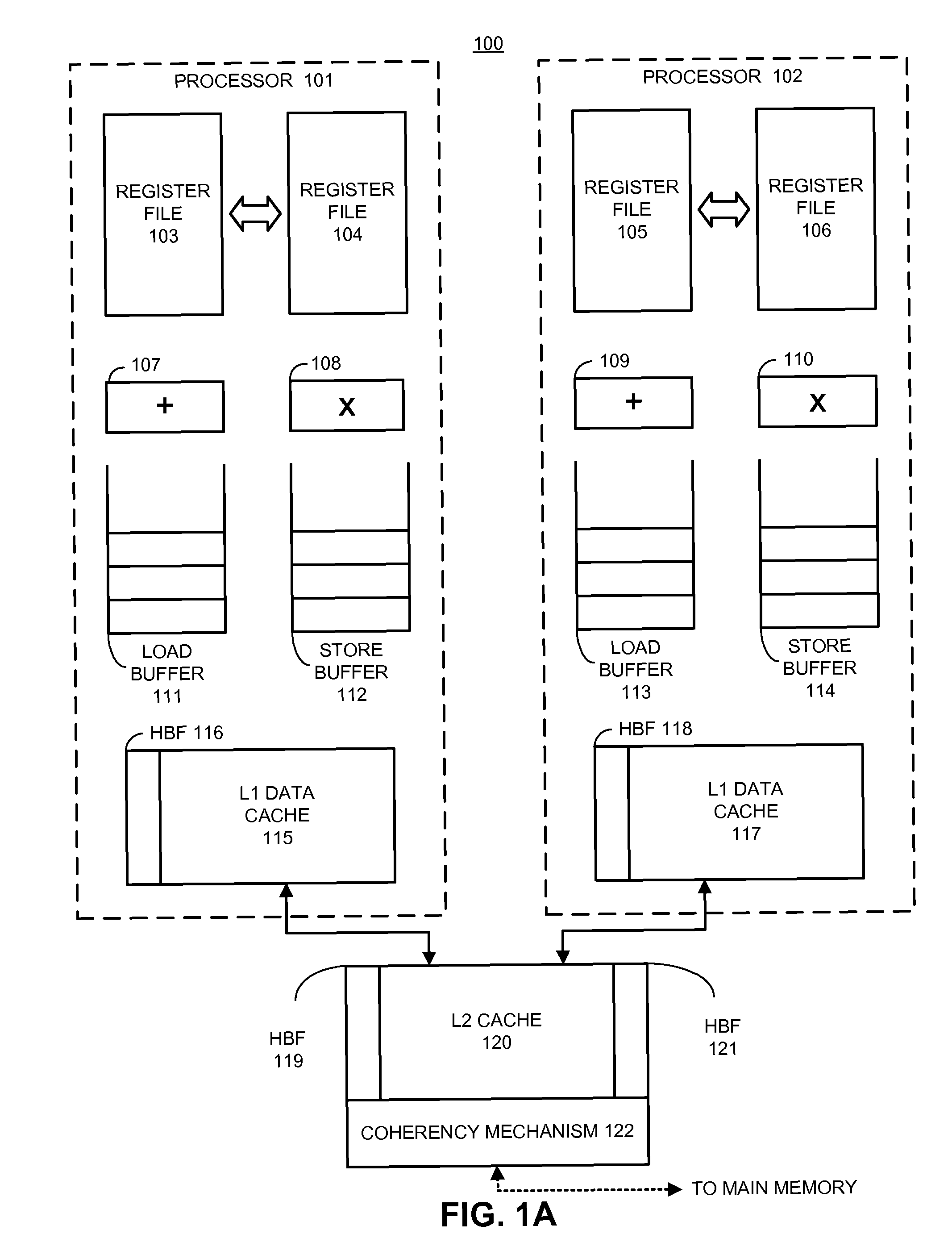
BACKGROUND[0001]1. Field[0002]The present embodiments relate to techniques for facilitating concurrency control in computer systems. More specifically, the present embodiments relate to a method and system for determining memory access conflicts during concurrent execution using hierarchical Bloom filters (HBFs).[0003]2. Related Art[0004]Computer system designers are presently developing mechanisms to support multi-threading within the latest generation of Chip-Multiprocessors (CMPs) as well as more traditional Symmetric Multiprocessors (SMPs). With proper hardware support, multi-threading can dramatically increase computational performance. However, as microprocessor performance continues to increase, the time spent synchronizing between threads (processes) is becoming a large fraction of overall execution time. In fact, as multi-threaded applications begin to use even more threads, this synchronization overhead often becomes the dominant factor in limiting application performance....

Claims


Application Information

Patent Timeline
Patent Type & Authority Patents(United States)
IPC IPC(8): G06F12/00G06F13/28G06F13/00
CPCG06F12/0811
Inventor CYPHER, ROBERT E.
Owner ORACLE INT CORP
Learn More