Hair cutting device with vacuum hair collection system

a hair collection and hair cutting technology, applied in the direction of manufacturing tools, metal-working hand tools, power-driven tools, etc., can solve the problem of clogging of the hair collection lin

Active Publication Date: 2013-07-16
LAUBE KIM
View PDF78 Cites 31 Cited by
  • Summary
  • Abstract
  • Description
  • Claims
  • Application Information

AI Technical Summary

Problems solved by technology

However, the conduit or channel for conveying cut hair, usually by means of a vacuum, for such systems generally have one or more constrictions that may cause the conduit to become clogged when hair flow volume may become excessive.

Method used


Image

  • Hair cutting device with vacuum hair collection system
  • Hair cutting device with vacuum hair collection system
  • Hair cutting device with vacuum hair collection system

Examples


Embodiment Construction

[0017]The following detailed description represents the best currently contemplated modes for carrying out the invention. The description is not to be taken in a limiting sense, but is made merely for the purpose of illustrating the general principles of the invention.

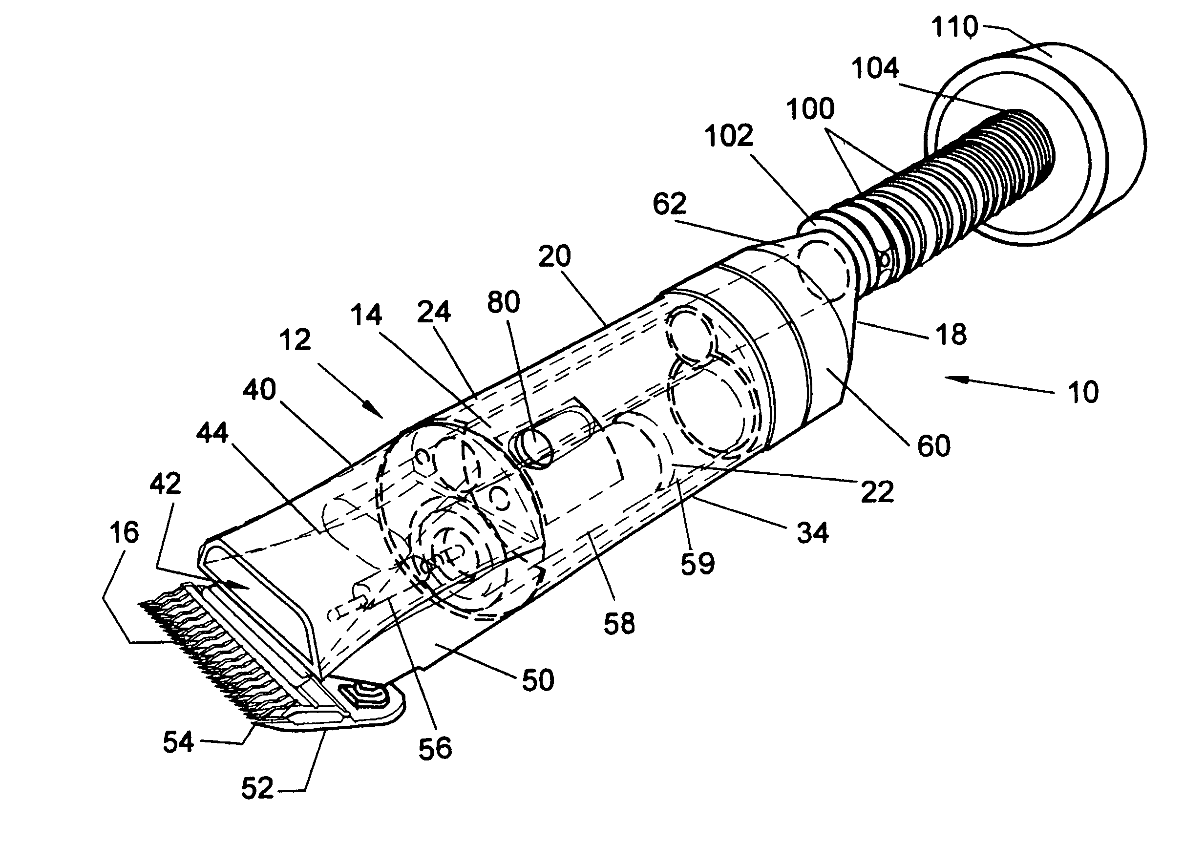
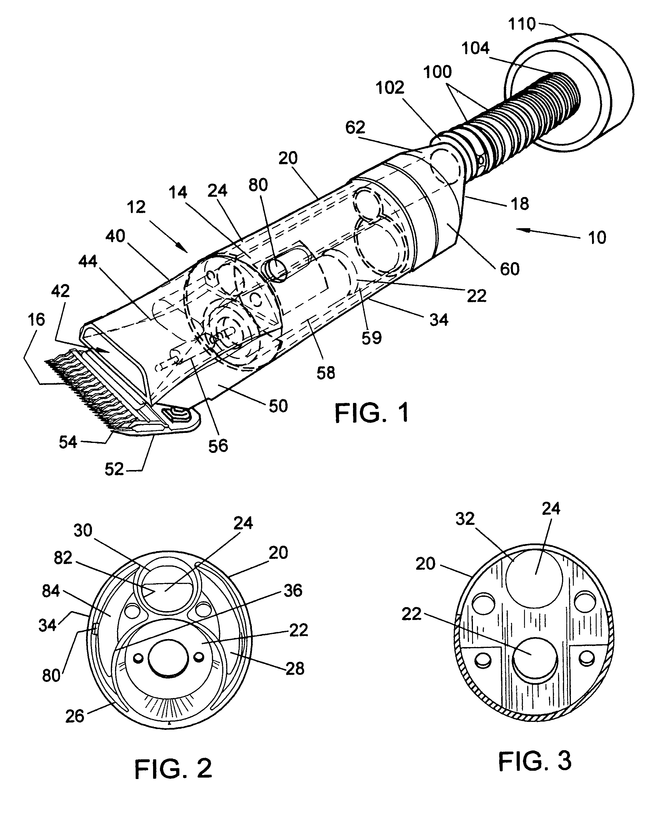
[0018]Referring to FIG. 1, a hair cutting device 10 may be a clipper 12 that may have a casing 20, a rear end closure 60, a front end housing 50 and a forward conduit element 40. The front end housing 50 may have a blade drive mechanism 56 disposed therein and the blade drive mechanism 56 may be engaged with a motor 58 that may be disposed in the casing 20. The front end housing 50 may support attachment of a cutting blade 52 for engagement with the blade drive mechanism 56. The motor may be connected to a battery 59 or other power source to power the clipper 12.

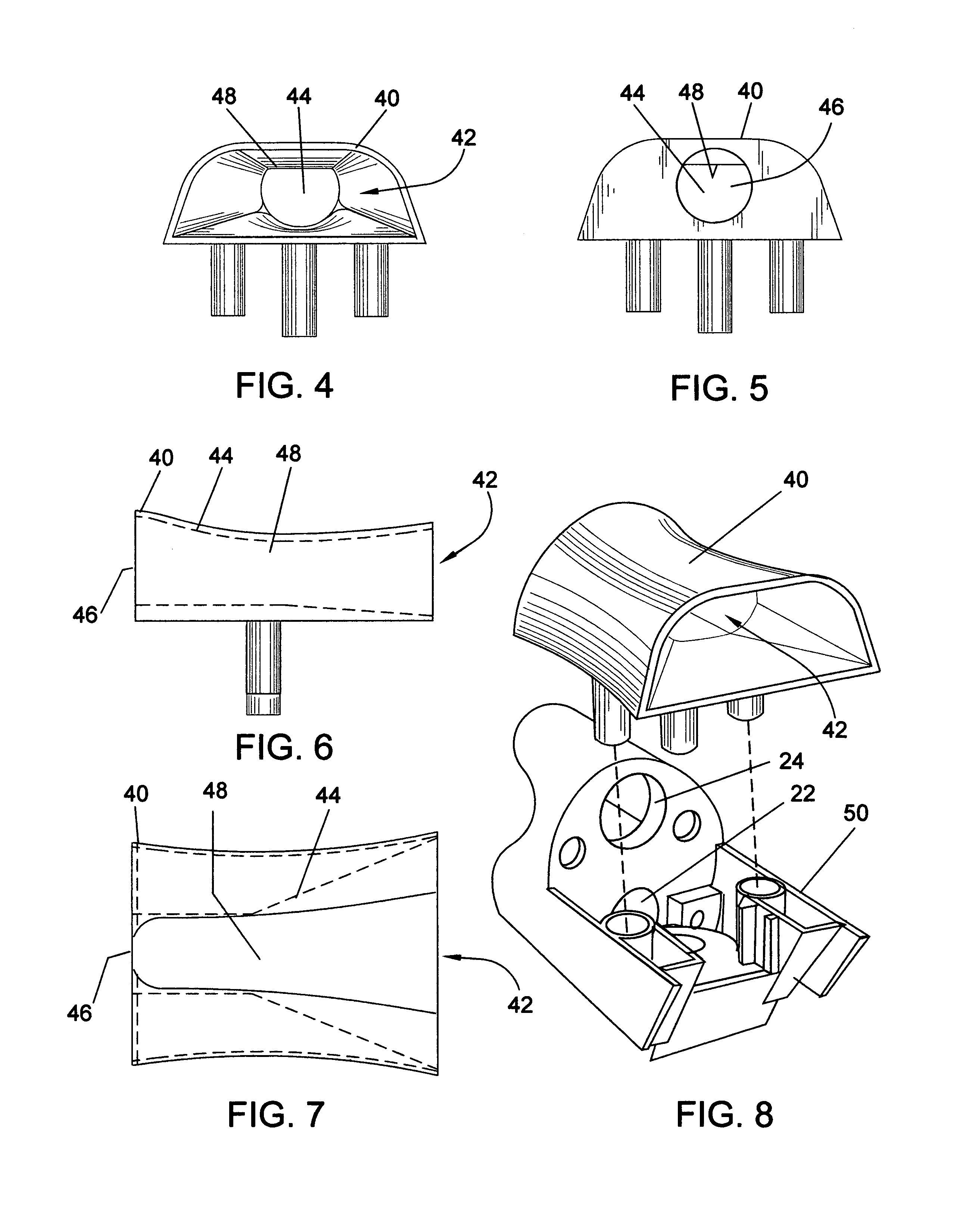
[0019]There may be a conduit 14 incorporated in the clipper 12 that may have a generally rectangular nozzle 42 at a forward end 16 and a rear opening 66 at a r...


PUM


Abstract

The present invention may be used for vacuum hair collection for a hair clipper. A conduit may be positioned in the clipper and may have a nozzle positioned adjacent to a cutting blade a forward end of the clipper. The conduit may have a rear opening at a rear end of the clipper. There may be a constriction section formed in the conduit adjacent the nozzle. The conduit may have a nondecreasing cross sectional interior dimension from the constriction section to the rear opening.

Description

BACKGROUND OF THE INVENTION[0001]This invention relates to devices used to cut hair or groom animals that include a system to collect the hair cuttings. The new device with vacuum system incorporates in a forward portion of a vacuum conduit a constriction or choke location positioned to cause any tendency to clog due to cut hair entrainment volume or other conditions to occur at the constriction location.[0002]Various hair collection systems for clippers may be known. However, the conduit or channel for conveying cut hair, usually by means of a vacuum, for such systems generally have one or more constrictions that may cause the conduit to become clogged when hair flow volume may become excessive. These constriction locations may be located in the conduit that may not be easily accessible to clear any clogged condition that may occur. A user may have to use a special tool or disassemble the clipper or vacuum conduit in order to clear a clogged condition.SUMMARY OF THE INVENTION[0003]...

Claims


Application Information

Patent Timeline
Patent Type & Authority Patents(United States)
IPC IPC(8): B26B19/44
CPCB26B19/44
Inventor LAUBE, KIM
Owner LAUBE KIM
Why Eureka
Try Eureka