Brake operation structure and brake/differential-lock operation structure

a technology of operation structure and brake, which is applied in the direction of foot actuation initiation, mechanical equipment, transportation and packaging, etc., can solve the problems of difficulty in operating the brake adjustment mechanism, the inability of the brake mechanism to generate sufficient braking power, and the change in the relationship between

Inactive Publication Date: 2013-07-16
YANMAR CO LTD
View PDF9 Cites 2 Cited by
  • Summary
  • Abstract
  • Description
  • Claims
  • Application Information

AI Technical Summary

Benefits of technology

[0032]Further, it is a second object of the present invention to provide a brake / differential-lock operation structure applicable to a working vehicle including a friction-plate type brake mechanism and a differential mechanism, wherein the brake / differential-lock operation structure includes a brake operation mechanism that rotates a brake pressing member of the friction-plate type brake mechanism about a rotational axis line into a brake actuation direction in accordance with manual operation, a differential-lock operation mechanism that switches a transmission state of the differential mechanism in accordance with manual operation, and a brake adjustment mechanism that adjusts an initial position of the brake pressing member around the rotational axis line at a time when the brake operation mechanism is not in operation, and wherein the brake / differential-lock operation structure is capable of shifting the differential mechanism into a differential-lock state in association with operation on the brake operation mechanism while allowing an independent operation of the differential-lock operation mechanism, and is further capable of preventing readjustment by the brake adjustment mechanism from influencing neither an operation path used for shifting the differential mechanism into the differential-lock state in association with the brake operation mechanism nor an operation path used for independently shifting the differential mechanism into the differential-lock state via the differential-lock operation mechanism.
[0096]The configuration makes it possible to reduce as much as possible a space required to arrange the first and second biasing members.

Problems solved by technology

However, if the group of friction plates are abraded way or worn out, there is caused change in the relationship between the manual operation amount of the brake operating member and the level of frictional contact in the group of friction plates (that is, the magnitude of braking power generated by the brake mechanism).
As a result, the brake mechanism may be incapable of generating sufficient braking power despite the fact that the brake operating member is manipulated by a predetermined amount.
However, the conventional brake operation structure had a problem of difficulty in operating the brake adjustment mechanism since the brake adjustment mechanism is disposed below the step of the working vehicle.
In the conventional configuration described above, a worker is required to go underneath the step or to detach the step in order to reach the brake adjustment mechanism 1200, so that adjustment of the brake adjustment mechanism 1200 has been a troublesome job.
As a result, the brake mechanism may be incapable of generating sufficient braking power despite the fact that the brake operating member is manually operated by the predetermined amount.
Furthermore, sufficient consideration has not been made to the conventional brake / differential-lock operation structure in regard to the timing of switching the differential mechanism from the differential state into the differential-lock state in association with the manual operation on the brake operating member.
Particularly in a state where the pair of drive axles receive traveling loads unequal to each other as in traveling across an inclined road, upon stopping the working vehicle by braking power of the brake mechanism, the braking power may not be effectively applied to the drive axle receiving a smaller traveling load, thereby increasing the danger of causing the working vehicle to turn in an unintended direction.
Therefore, one of driving wheels that is positioned on an outer side with turning center as a reference unfavorably slips.

Method used


Image

  • Brake operation structure and brake/differential-lock operation structure
  • Brake operation structure and brake/differential-lock operation structure
  • Brake operation structure and brake/differential-lock operation structure

Examples


first embodiment

[0185]Described below is a preferred embodiment of the present invention with reference to the accompanying drawings.

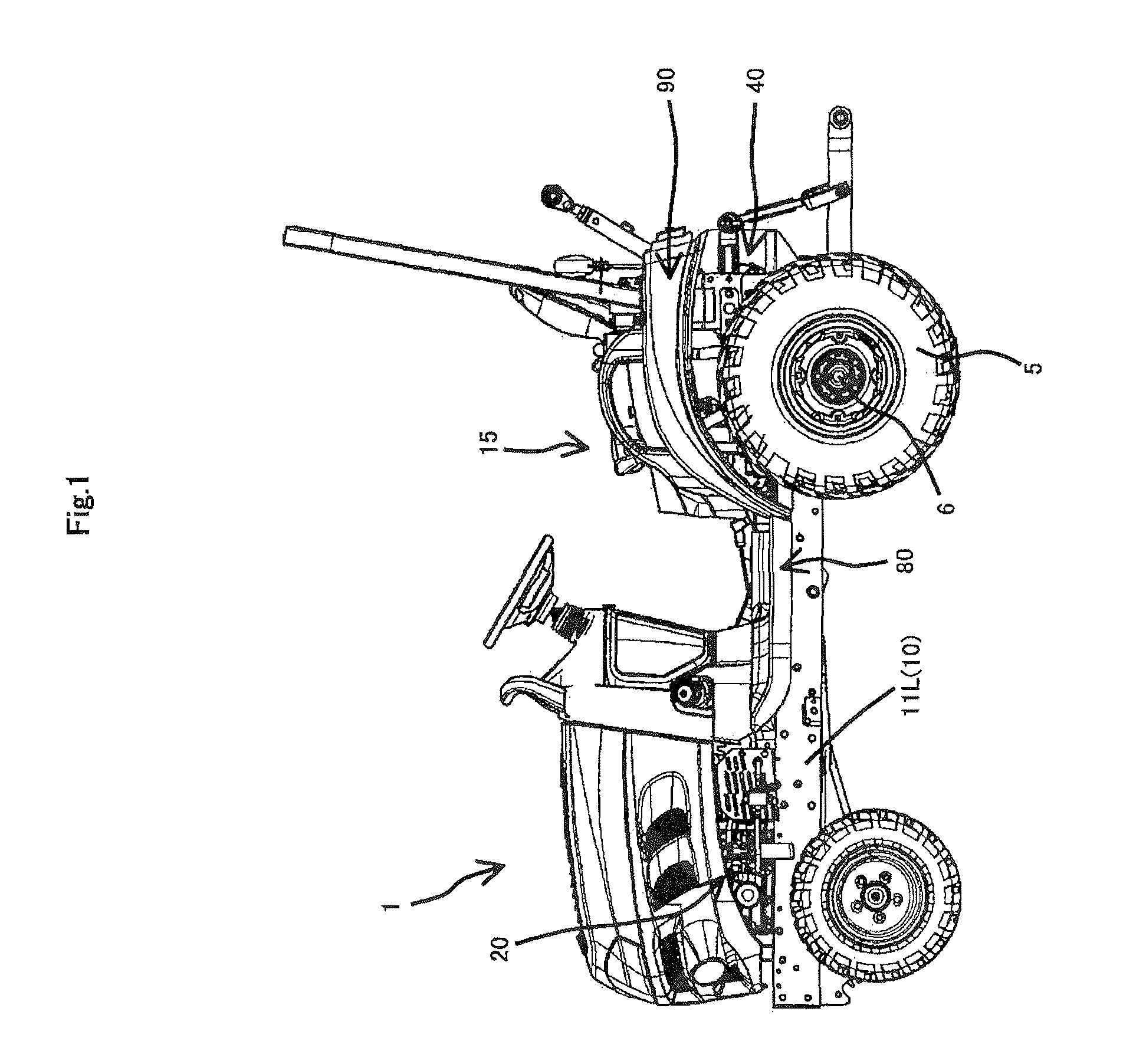
[0186]FIG. 1 is a side view of a working vehicle 1 to which a brake / differential-lock operation structure according to the present embodiment is applied.

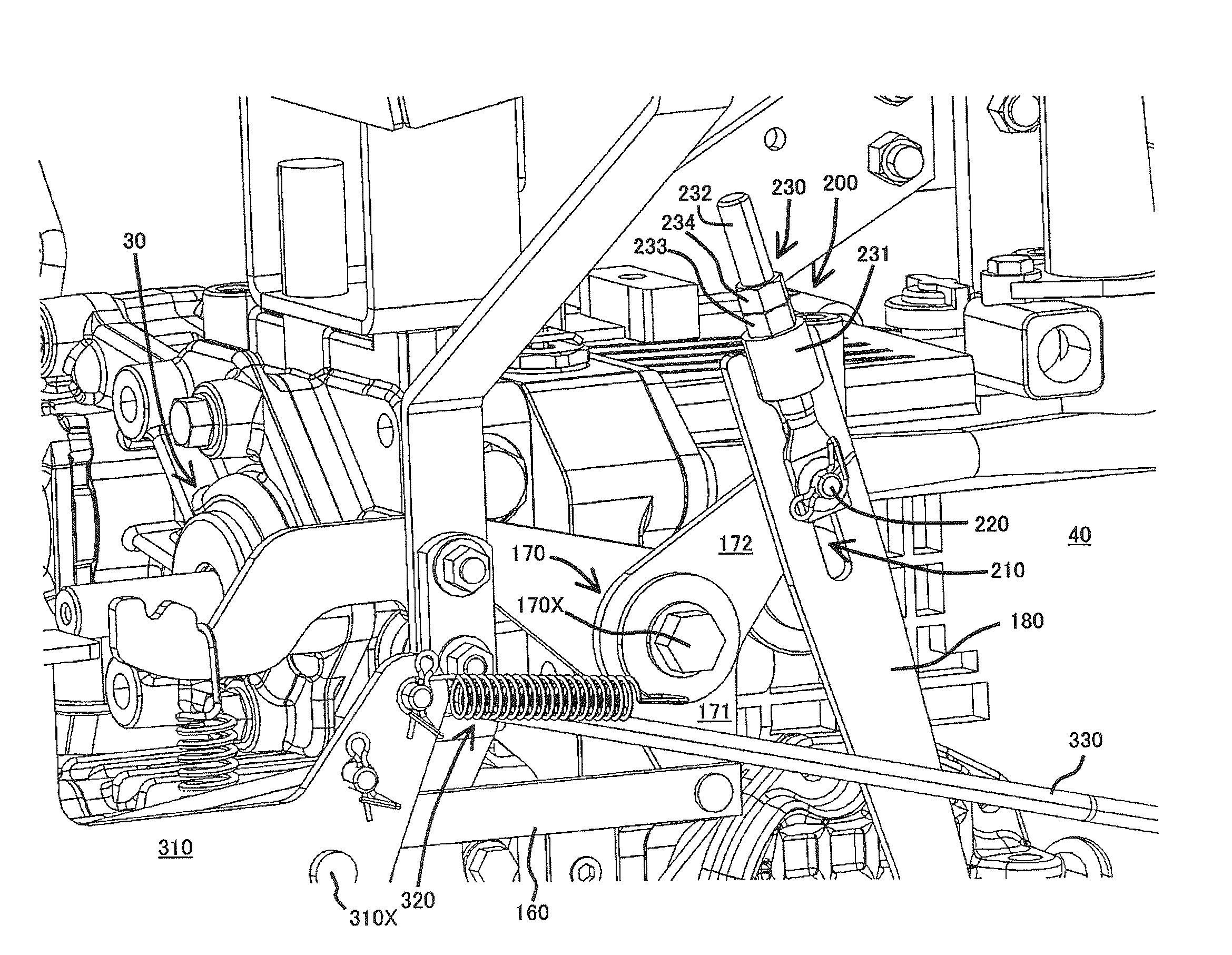
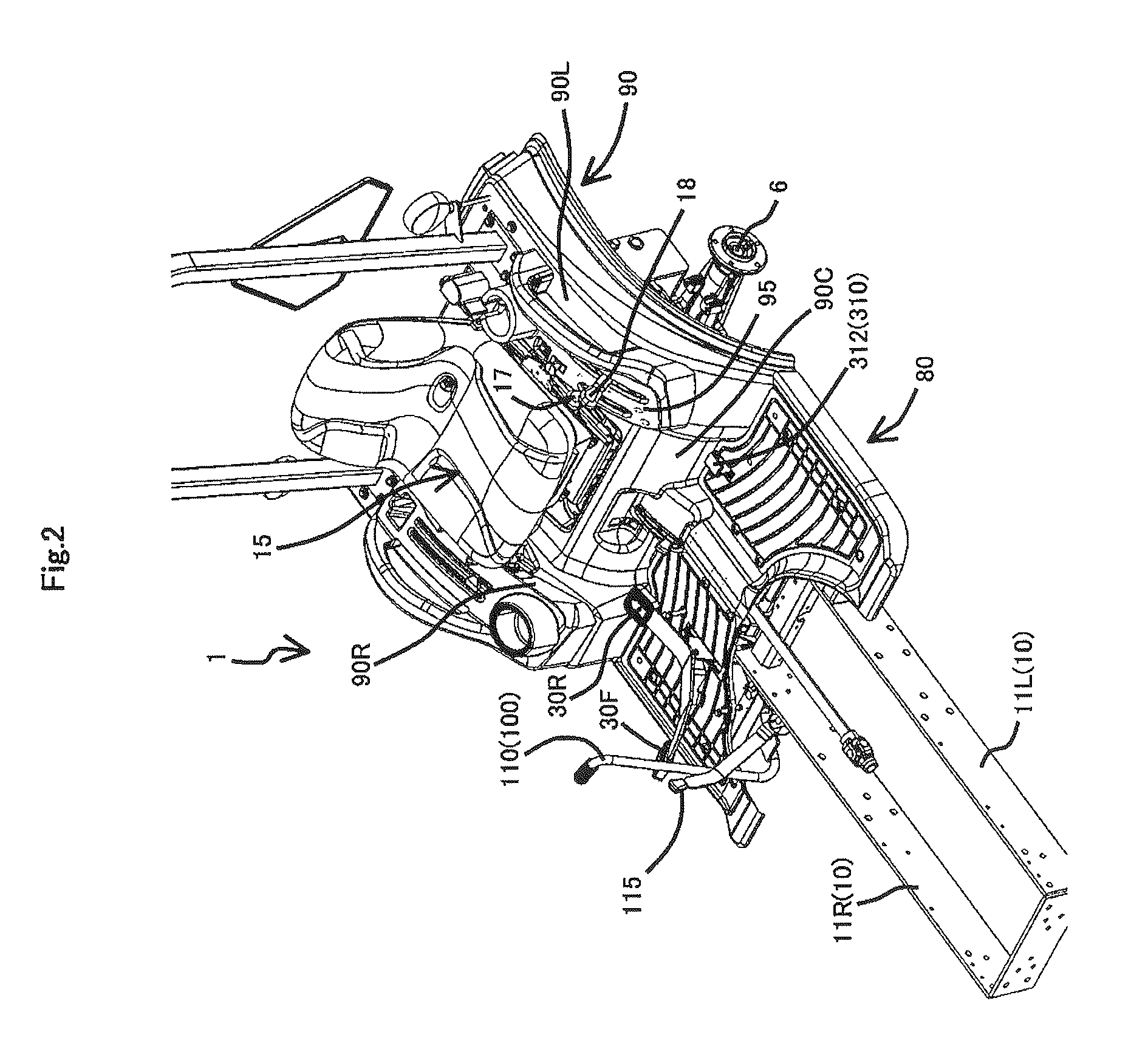
[0187]FIG. 2 is a partial perspective view of the working vehicle 1, and FIG. 3 is a partial perspective view of the working vehicle 1 with a step 80 and a fender 90 being removed from the illustration in FIG. 2.

[0188]As shown in FIGS. 1 to 3, the working vehicle 1 includes a vehicle frame 10 that has a pair of left and right main frames 11L and 11R each extending along the vehicle lengthwise direction, a driving power source 20 that is disposed on a front portion of the vehicle frame 10, a transmission case 40 that is connected to a rear portion of the vehicle frame 10, an HST 30 that is supported on a front surface of the transmission case 40 while being operatively connected to the driving power source 20, a travel...

second embodiment

[0366]Described below is a preferred embodiment of the present invention with reference to the accompanying drawings.

[0367]FIG. 18 is a side view of a working vehicle 1B to which a travel speed operation apparatus 100B according to the present embodiment is applied.

[0368]FIGS. 19 and 20 are front perspective views of the travel speed operation apparatus 100B according to the present embodiment, and FIGS. 19 and 20 are perspective views as viewed from left and right sides with a forward travel direction of the working vehicle being as a reference, respectively.

[0369]As shown in FIGS. 18 to 20, the working vehicle 1B includes a vehicle frame 10B, a driving power source 20B that is disposed on a front portion of the vehicle frame 10B, an HST 30B that is operatively connected to the driving power source 20B, a transmission case 40B that is connected to a rear portion of the vehicle frame 10B, and a travel brake mechanism (not shown) provided in the transmission case 40B.

[0370]The HST 30...

third embodiment

[0503]Described below is a hood structure of a working vehicle according to an embodiment of the present invention. It is noted that the technical scope of the present invention is not limited to the embodiment but may be applied widely to the entire scope of the technical idea truly intended from the present invention, which will be apparent from the matters described in the specification and the drawings thereof.

[0504]FIG. 32 is a side view of a working vehicle (tractor) to which the hood structure according to the present embodiment is applied.

[0505]As shown in FIG. 32, the hood structure has a hood 31C openable about a pivot axis along the vehicle width direction. FIG. 32 indicates the positions of the closed and opened hood 31C by solid and two-dot chain lines, respectively.

[0506]FIG. 33 is a side view of the front portion of the working vehicle in the state where the hood 31C is located at the open position.

[0507]Further, FIGS. 34 and 35 are enlarged side views of the front po...


PUM


Abstract

The present invention provides a brake operation structure capable of realizing facilitation of adjustment work of a brake operation mechanism for operating a brake mechanism based on manual operation. The brake operation structure includes a brake operation mechanism that rotates a brake pressing member of the brake mechanism about a rotational axis line into a brake actuation direction in accordance with manual operation, and a brake adjustment mechanism that adjusts an initial position of the brake pressing member around the rotational axis line at a time when the brake operation mechanism is not in operation. The brake adjustment mechanism is inserted in the brake operation mechanism at a position allowing the brake adjustment mechanism to be accessed from above a fender trough an opening that is provided at the fender for allowing a driver's seat support frame to be mounted.

Description

BACKGROUND OF THE INVENTION[0001]1. Field of the Invention[0002]The present invention relates to a brake operation structure applied to a working vehicle including a friction-plate type brake mechanism, a transmission case that accommodates the brake mechanism, a driver's seat that is disposed above the transmission case, and a fender that covers a side of the driver's seat.[0003]The present invention also related to a brake / differential-lock operation structure applied to a working vehicle including a friction-plate type brake mechanism and a differential mechanism capable of switching between a differential state and a differential-lock state.[0004]2. Background Art[0005]There is known a brake operation structure used for operating a friction-plate type brake mechanism that includes group of friction plates and a brake pressing member and is configured so that, in accordance with rotation of the brake pressing member about a rotational axis line into a brake actuation direction, t...

Claims


Application Information

Patent Timeline
Patent Type & Authority Patents(United States)
IPC IPC(8): B60T7/04B60K17/04
CPCB60T11/04
Inventor MATSUBAYASHI, TOSHIKAZU
Owner YANMAR CO LTD
Why Eureka
Try Eureka