
Impulse noise mitigation under out-of-band interference conditions

a technology of impulse noise and interference conditions, applied in the field of wireless communication receivers, can solve the problems of unreliable detection of impulse noise, and inability to detect the presence of impulse noise, so as to reduce the energy of other noise interference signals, and mitigate impulse noise and other noise interference signals.

Active Publication Date: 2013-07-16
MAXLINEAR INC
View PDF37 Cites 7 Cited by
  • Summary
  • Abstract
  • Description
  • Claims
  • Application Information

AI Technical Summary

Benefits of technology

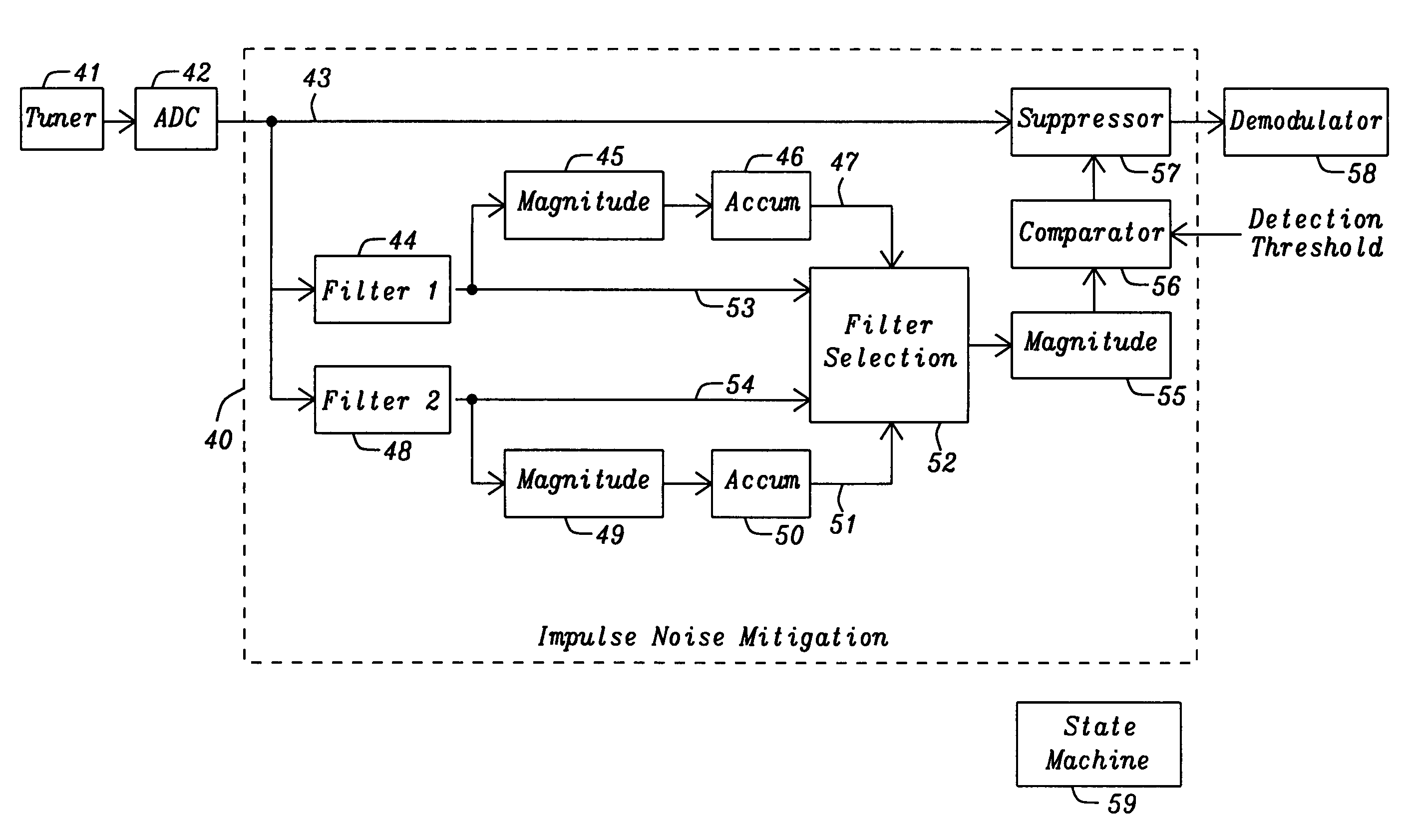
[0013]It is an objective of the present invention to provide two complex filters to improve the frequency domain impulse mitigation.
[0015]It is further an objective of the present invention to measure the mean magnitude over a time interval T of each of the two high pass filters in order to select which of the two filters to use to detect and mitigate impulse noise.
[0016]In the present invention two complex high pass filters are used to mitigate impulse noise and other noise interferer signals. The response of each individual filter is measured over a time period T to determine which filter provides the best response. This measurement is the mean magnitude of the noise signal that is being removed from the signal being connected to the output of an impulse noise mitigation circuit, whereupon the filter producing the lowest mean magnitude value is chosen for impulse noise mitigation. This selection also dramatically reduces energy of other noise interferer signals. It should be noted that one of the two filters admits frequency components higher than the desired bandwidth on the positive frequency axis and the other of the two filters only admits frequency components lower than the desired signal bandwidth.

Problems solved by technology

Noise and in particular impulse noise, which is generated in short bursts, can be disruptive to data (broadcasts) that are processed through an analog receiver and translated into a digital format to produce a quality output as one might experience in a received radio transmission.
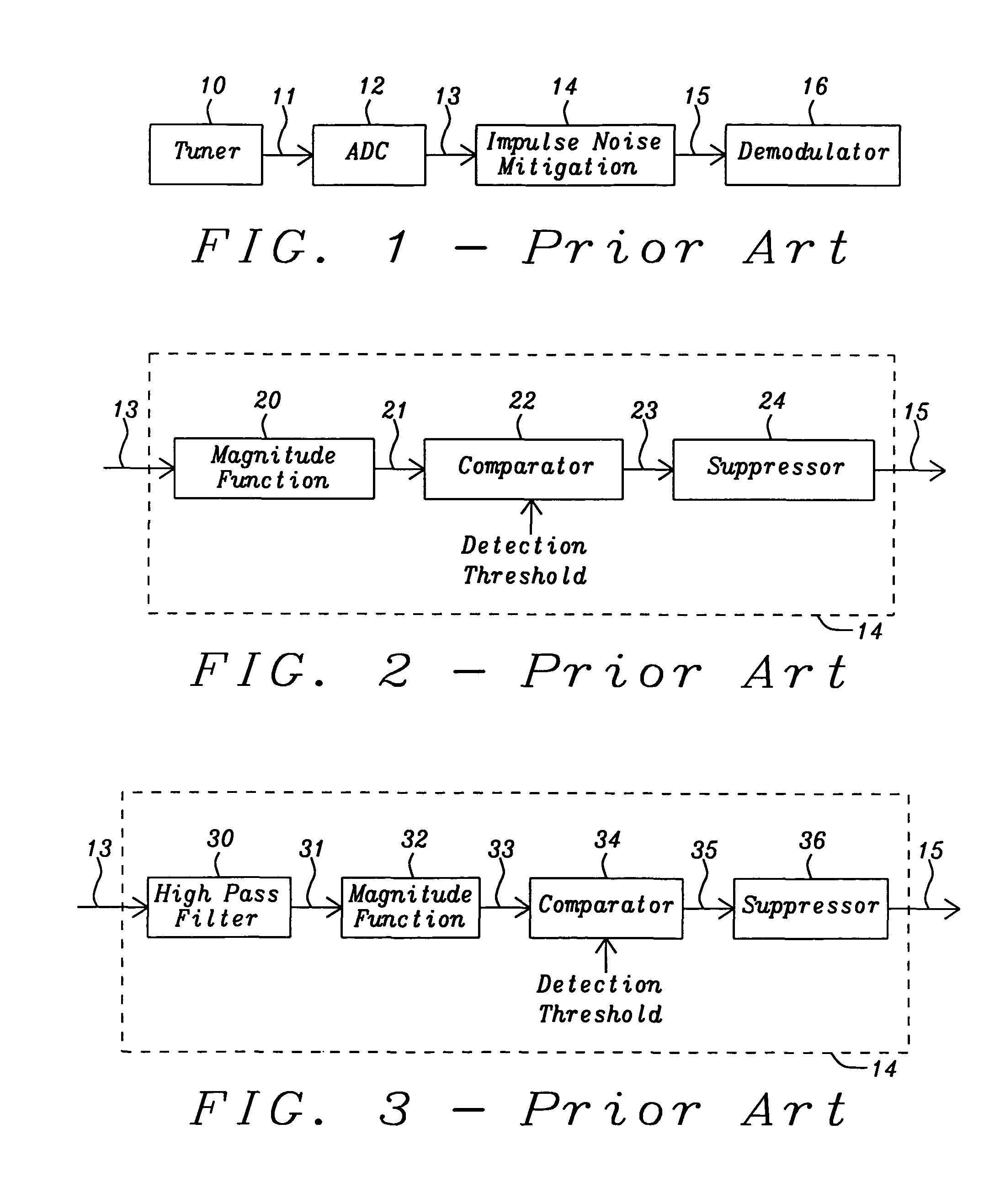
A shortcoming of the time domain method of impulse noise mitigation, shown in FIG. 2, is the inability to detect the presence of impulse noise under normal or relatively high carrier to interference ratio.
The main drawback of the frequency domain method shown in FIG. 3 is the inability to detect the presence of impulse noise under out of band interferers, especially adjacent interferers, where the signal at the output of the magnitude function 33 will contain the energy of both the impulse noise and the interferers thus making the detection of impulse noise unreliable.

Method used


Image

  • Impulse noise mitigation under out-of-band interference conditions
  • Impulse noise mitigation under out-of-band interference conditions
  • Impulse noise mitigation under out-of-band interference conditions

Examples


Embodiment Construction

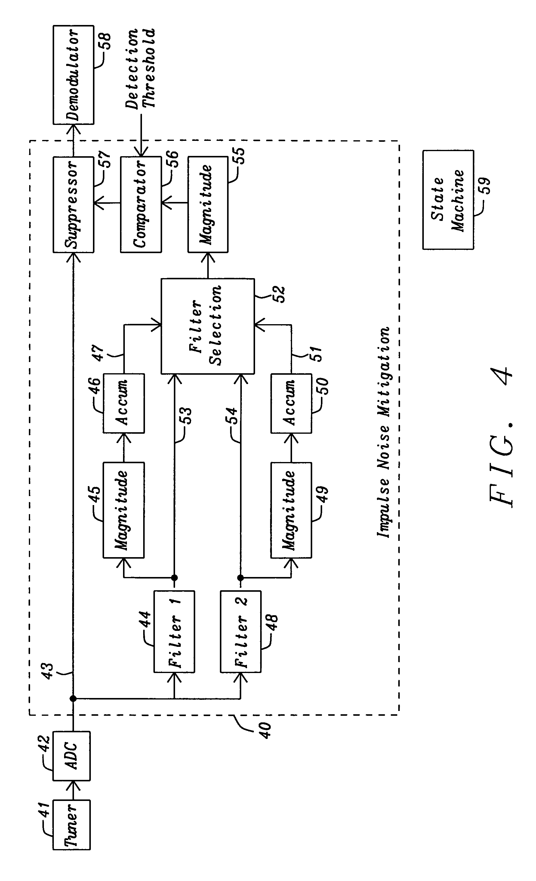
[0024]In FIG. 4 is shown a block diagram of the frequency domain impulse noise mitigation 40 of the present invention. The output of an analog tuner 41 is connected to an ADC 42 to convert the receiver analog signal into a digital signal. The output 43 of the ADC 42 is coupled to the impulse noise mitigation circuit 40 for the purpose of impulse noise detection. The output of the ADC 43 is also connected to the suppressor circuit 57. When impulse noise is detected from signal samples applied to the filters 44 and 48, these samples will be flagged with an impulse noise indicator, and then the mitigation is applied to the corresponding ADC output connected directly to the suppressor circuit 57.

[0025]Within the impulse noise mitigation circuitry 40 are two complex high pass filters 44 and 48, filter 1 and filter 2 respectively. Each of filter output is connected to a magnitude function 45 and 49, respectively, in which outputs of the magnitude functions are connected to accumulator cir...


PUM


Abstract

A noise abatement method and system for impulse noise in an RF receiver where the RF analog signal is converted to a digital signal prior to being connected to a demodulator. Two filters are used to detect impulse noise signals even under out-of-band interferer conditions, and prevent the impulse noise from reaching the input to the demodulator. A first of the two filters detects impulse noise using signals lower than the frequency bandwidth of the desired signal, and a second of the two filters detects impulse noise using signals higher the frequency bandwidth of the desired signal. A mean magnitude of the signal is detected over a predetermined time T and is used to select which filter to use for noise abatement.

Description

[0001]This application claims priority to Provisional Patent Application Ser. No. 61 / 277,315, filed on Sep. 23, 2009, which is herein incorporated by reference in its entirety.BACKGROUND OF THE INVENTION[0002]1. Field of Invention The present invention is related to a wireless communication receiver and in particular impulse noise mitigation.[0003]2. Description of Related Art[0004]Noise and in particular impulse noise, which is generated in short bursts, can be disruptive to data (broadcasts) that are processed through an analog receiver and translated into a digital format to produce a quality output as one might experience in a received radio transmission. The impulse noise can be caused by many modern day sources in which ignition systems and domestic appliances represent a couple of sources. Elimination or mitigation of impulse noise is essential to a clear reproduction of the received analog signal into a digital signal format.[0005]US Patent Application Publication 2010 / 00541...

Claims


Application Information

Patent Timeline
Patent Type & Authority Patents(United States)
IPC IPC(8): H03H7/40H04B15/00
CPCH04B1/10H04B1/1036
Inventor LO, ANDYKANG, SUGBONG
Owner MAXLINEAR INC
Learn More