Merge/diverge conveying apparatus and method of providing a conveyor belt for a merge/diverge apparatus

Active Publication Date: 2013-07-23
TRANSNORM SYST
View PDF12 Cites 10 Cited by
  • Summary
  • Abstract
  • Description
  • Claims
  • Application Information

AI Technical Summary

Benefits of technology

[0024]Unlike prior art conveyor belts for merge or diverge conveyors, use of the present conveyor belt allows for quicker installation and removal of the conveyor belt than previously existed. Instead of the two to

Problems solved by technology

Within days after commencement of operation, use of steel clipped conveyor belts r

Method used


Image

  • Merge/diverge conveying apparatus and method of providing a conveyor belt for a merge/diverge apparatus
  • Merge/diverge conveying apparatus and method of providing a conveyor belt for a merge/diverge apparatus
  • Merge/diverge conveying apparatus and method of providing a conveyor belt for a merge/diverge apparatus

Examples


Example

[0050]The disclosure hereof is detailed to enable those skilled in the art to practice the invention, and the embodiments published herein merely exemplify the present invention and do not limit the scope of the claims appended hereto.

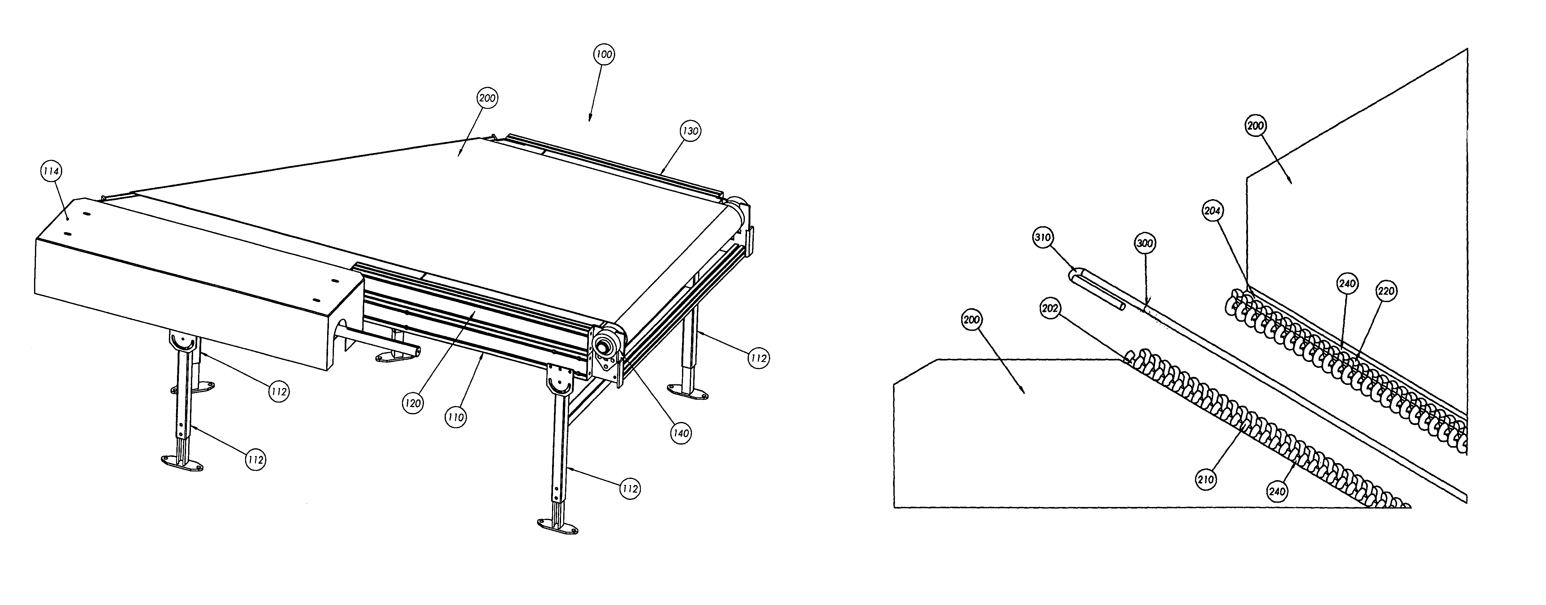
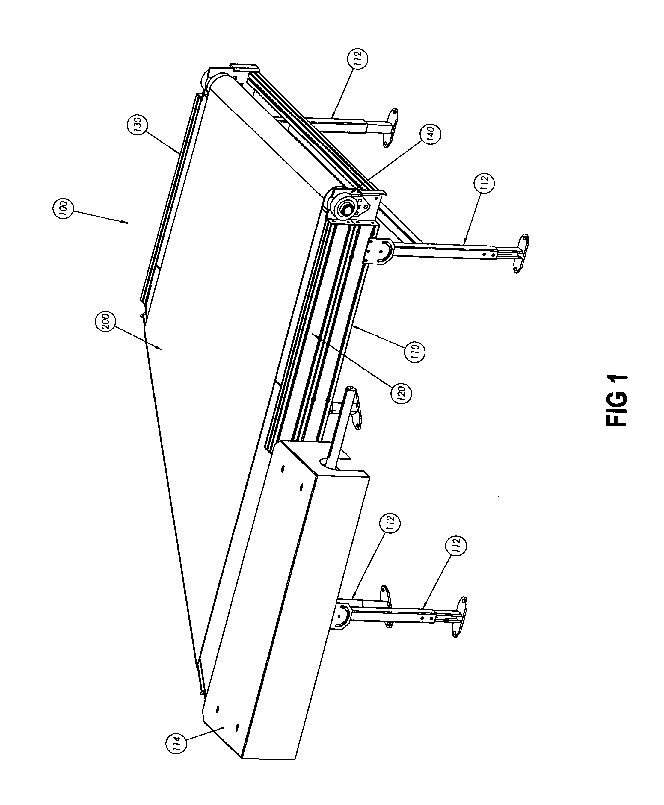
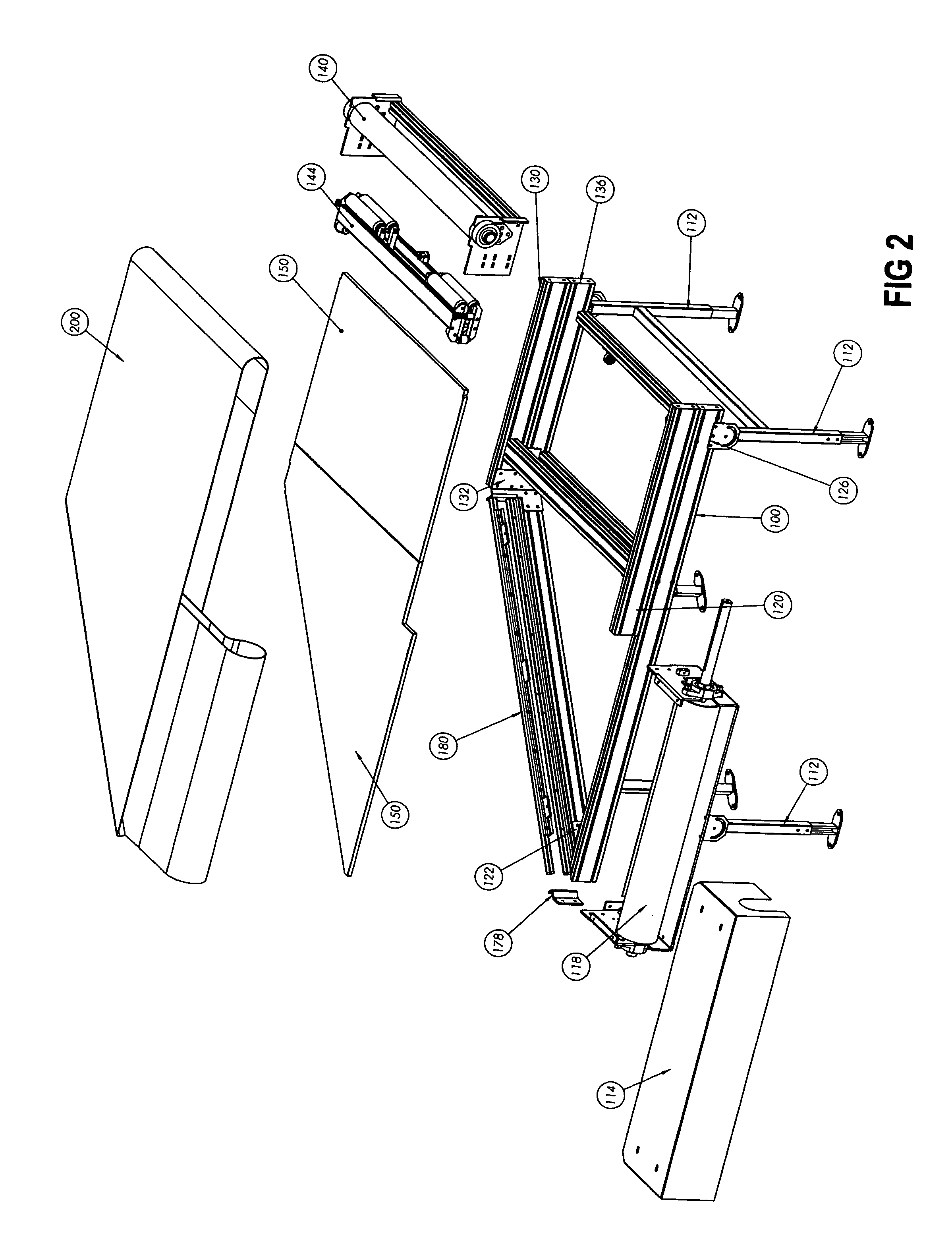
[0051]The present invention is primarily directed toward the practice of an angled merge or an angled diverge conveying apparatus and novel and nonobvious conveyor belts associated with the angled merge or an angled diverge conveying apparatus. It is believed that all prior art angled merge or angled diverge conveyors have utilized metallic components, such as steel, to lace the ends of prior art conveyor belts together. Due to the stresses associated with circulation of prior art conveyor belts about the angled merge or angled diverge conveyors, the nose bars of the prior art angled merge or angled diverge conveyors were easily worn down by the circulating prior art conveyor belts. The present invention provides a conveyor belt that can be used with a...


PUM

PropertyMeasurementUnit
Timeaaaaaaaaaa
Angleaaaaaaaaaa
Angleaaaaaaaaaa

Abstract

A conveyor belt for use with a merge or diverge conveying apparatus and a method of providing a new conveyor belt to the conveying apparatus. Polymeric loops attached to each end of the conveyor belt attach the ends of the conveyor belt to each other. Visible wear and tear to the nose bar of the merge or diverge conveying apparatus is reduced when compared to prior art conveyor belts for merge or diverge conveyors.

Description

BACKGROUND OF THE INVENTION[0001]1. Field of the Invention[0002]Among other things, the present invention includes a method of providing a new conveyor belt for a merge or diverge conveyor as well as a conveyor belt for use with a merge or diverge conveyor. The conveyor belt is provided with one or more clusters of polymeric loops that are interlocked with each other after the belt has been threaded about the merge or diverge conveyor. For ease of securing the conveyor belt to the merge or diverge conveyor, the polymeric loops can be joined together in a zipper-like manner. The combination of the polymeric loops and the polymeric flexible pin reduce visible wear and tear to the nose bar of the merge or diverge conveying apparatus when compared to the prior art conveyor belts for merge or diverge conveyors.[0003]2. Description of the Previous Art[0004]Any discussion of references cited in this Description of the Previous Art merely summarizes the disclosures of the cited references a...

Claims


Application Information

Patent Timeline
IPC IPC(8): B23P11/02
CPCB65G15/02B65G15/34Y10T29/49867
Inventor LANGSDORF, JOHNCLINE, GARY
Owner TRANSNORM SYST
Why Eureka
Try Eureka