Suspension device

a suspension device and suspension technology, applied in the direction of shock absorbers, mechanical devices, transportation and packaging, etc., can solve the problems of deteriorating vehicle ride quality, difficult movement of hydraulic dampers, and difficulty in moving conventional suspension devices, so as to improve the reliability of the actuator, improve the ride quality of the vehicle, and improve the reliability of the suspension device.

Inactive Publication Date: 2013-07-23
KYB CORP
View PDF16 Cites 29 Cited by
  • Summary
  • Abstract
  • Description
  • Claims
  • Application Information

AI Technical Summary

Benefits of technology

[0006]In view of the above-mentioned defect of the conventional suspension device, the present invention has an object to provide a suspension device, capable of improving reliability and vehicle ride quality.
[0009]That is, the bearing is in slidable contact with a position which does not affect the extension / contraction of the fluid pressure damper to ensure smooth extension / contraction of the fluid pressure damper. Thus, in this suspension device, the fluid pressure damper is actively extended / contracted, upon input of high frequency vibration, to absorb the vibration, whereby the vibration isolation property to the sprung member is improved to improve the vehicle ride quality.
[0010]Further, since the bearing does not interfere with the extension / contraction of the fluid pressure damper upon input of high frequency vibration, direct action of impact force on the actuator is suppressed. Accordingly, the motor and the motion conversion mechanism can be protected to improve the reliability of the actuator that is an essential component of the suspension device, and the reliability of this suspension device can be improved by dissolving the defect of the conventional suspension device.

Problems solved by technology

In this suspension device, however, since an annular bearing is doubly interposed between an outer cylinder which covers the motor and the motor to guide the linear motion of the motor, the presence of the bearing makes the hydraulic damper difficult to move, when absorbing the high frequency vibration by the hydraulic damper and the springs holding the motor, to hinder the vibration absorption, and can cause deterioration of vehicle ride quality resulting from transmission of the vibration to the sprung member.
Further, since the bearing interferes with vertical motion of the motor, large acceleration tends to act on the actuator, and when high frequency vibration is input, each part of the actuator is directly vibrated by this high frequency vibration.
Consequently, the conventional suspension device is problematic in the point of the reliability as shock absorber, partly for the reason that high frequency vibration is large in acceleration.

Method used


Image

  • Suspension device
  • Suspension device

Examples


Embodiment Construction

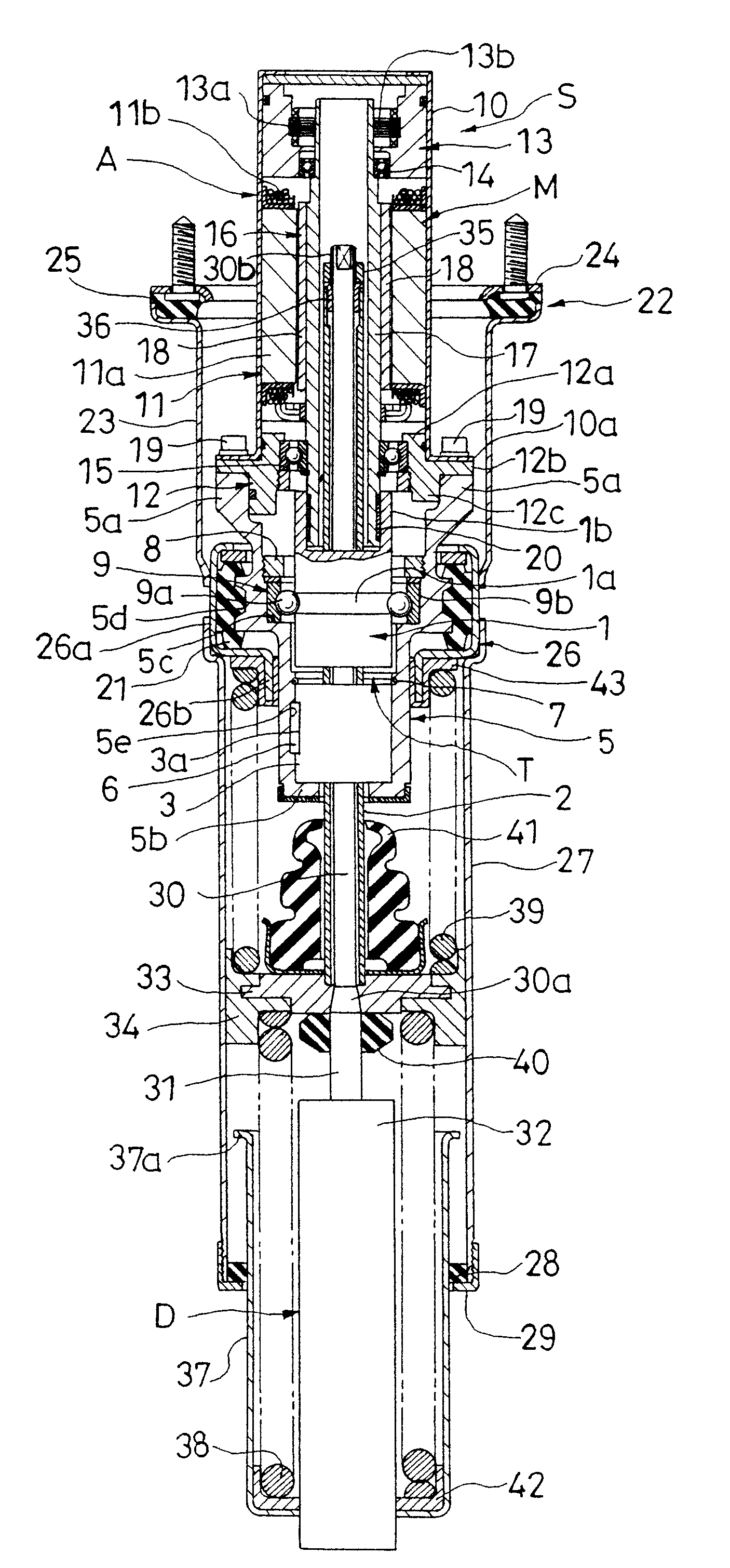
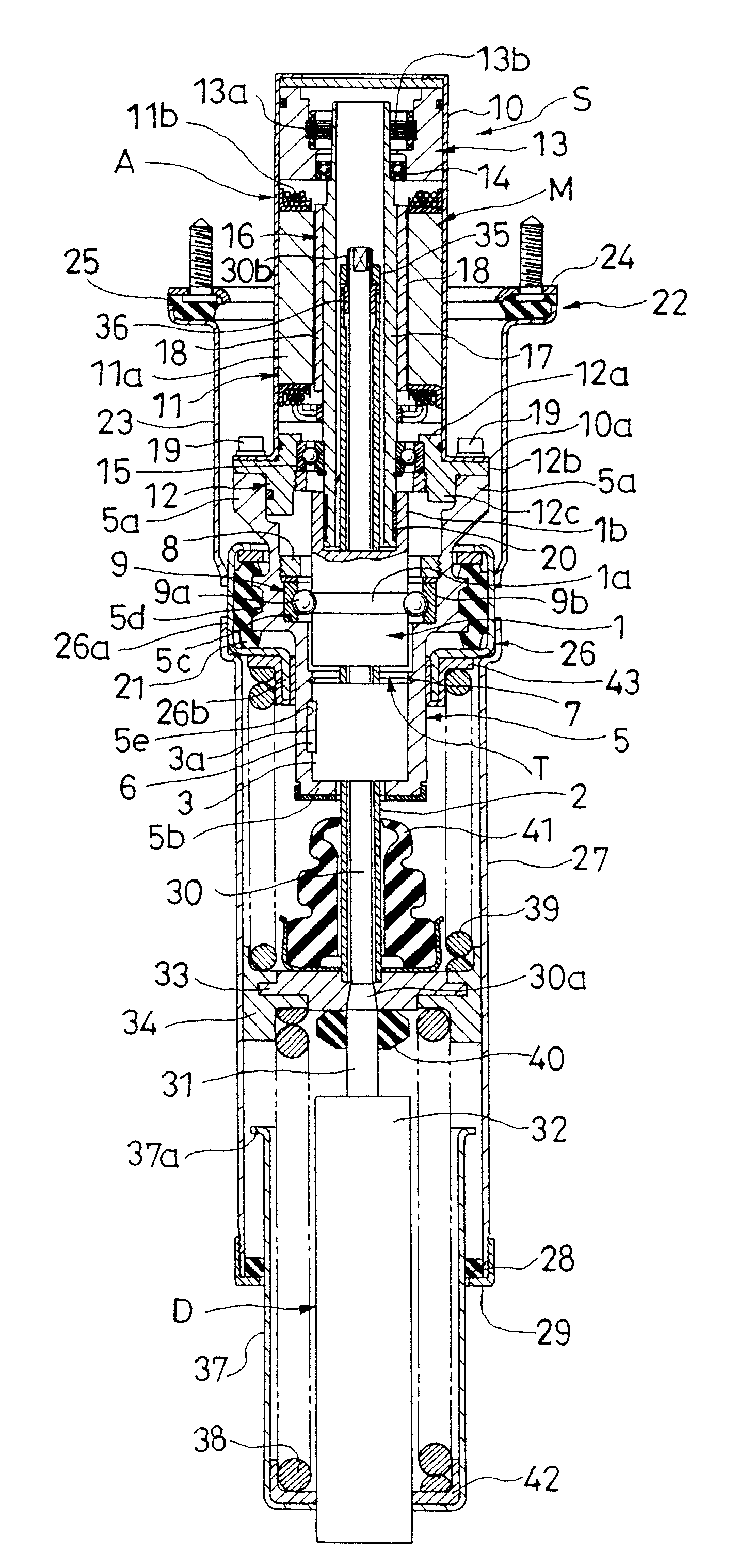
[0012]A suspension device S according to one preferred embodiment of the present invention basically comprises, as shown in FIG. 1, an actuator A including a motion conversion mechanism T for converting a linear motion to a rotational motion, and a motor M connected to a ball screw nut 1 that is a rotary member which performs the rotational motion in the motion conversion mechanism T; a fluid pressure damper D connected to a threaded shaft 2 that is a linear motion member which performs the linear motion in the motion conversion mechanism T; an outer cylinder 27 connected to the actuator A; and an annular bearing 34 attached to a rod 31 connected to the threaded shaft 2 that is the linear motion member of the fluid pressure damper D and slidably contacting with the inner circumference of the outer cylinder 27.

[0013]This suspension device S can function as an actuator since the threaded shaft 2 can be linearly moved in the vertical direction in FIG. 1 by driving and rotating the ball...


PUM


Abstract

A suspension device (S) comprises: an actuator (A) including a motion conversion mechanism (T) for converting a linear motion to a rotational motion and a motor (M) connected to a rotary member (1) which performs the rotational motion in the motion conversion mechanism (T); a fluid pressure damper (D) connected to a linear motion member (2) which performs the linear motion in the motion conversion mechanism (T); an outer cylinder (27) connected to the actuator (A); and a bearing (34) attached to a rod (31) or a cylinder (32) connected to the linear motion member (2) of the fluid pressure damper (D) and slidably contacting with the inner circumference of the outer cylinder (27). This suspension device can improve reliability and vehicle ride quality.

Description

FIELD OF THE INVENTION[0001]The present invention relates to an improved suspension device for suppressing relative movement between a vehicle body and an axle by an electromagnetic force generated in a motor.DESCRIPTION OF THE RELATED ART[0002]This kind of suspension device comprises, for example, as disclosed in Japanese Patent Application Laid-Open No. 08-197931, a suspension spring for elastically supporting the vehicle body or a sprung member of a vehicle; an actuator including a threaded shaft rotatably screwed to a ball screw nut connected to the axle or an unsprung member of the vehicle, and a motor interposed between a pair of springs while being connected to one end of the threaded shaft, and elastically supported by the sprung member; and a hydraulic damper fixed to the sprung member to damp vertical vibration of the actuator, in which the relative movement between the vehicle body and the axle is actively controlled by the thrust of the actuator.DISCLOSURE OF THE INVENTI...

Claims


Application Information

Patent Timeline
Patent Type & Authority Patents(United States)
IPC IPC(8): F16F15/03
CPCB60G15/067B60G15/068B60G17/021F16F15/03B60G2204/124F16F2232/06B60G2204/42B60G2300/60B60G2204/40
Inventor KONDO, TAKUHIRO
Owner KYB CORP
Why Eureka
Try Eureka