Hydraulic shock absorber

a technology of shock absorber and communication passage, which is applied in the direction of shock absorbers, vibration dampers, springs/dampers, etc., can solve the problems of deteriorating ride quality of vehicles, high manufacturing costs, and complicated manufacturing work of communication passages provided to piston rods

Inactive Publication Date: 2012-11-06
HONDA MOTOR CO LTD
View PDF12 Cites 14 Cited by
  • Summary
  • Abstract
  • Description
  • Claims
  • Application Information

AI Technical Summary

Benefits of technology

[0021]The present invention has been made in view of the above problems, and a first object thereof is to provide a hydraulic shock absorber including a piston rod which has a communication passage that can be formed easily.
[0022]A second object of the present invention is to provide a hydraulic shock absorber which is allowed to enhance a ride quality of a vehicle by preventing its damping force from sharply increasing when the vehicle run over large bumps on an un-maintained road and a large input is instantaneously applied to the vehicle.
[0023]A third object of the present invention is to provide a hydraulic shock absorber whose configuration is simple and which is allowed to reduce friction resistance of the piston when the piston rod slides and to enhance the ride quality of a vehicle by continuously changing its damping force.

Problems solved by technology

On the other hand, the manufacturing work of the communication passage provided to the piston rod is complicated and its manufacturing cost is also high because the piston rod has to be formed hollow to form a flow passage extending in the axial direction, and radial direction paths have to be also provided which extend from the outer circumferential surface of the piston rod to the flow passage extending in the axial direction.
The manufacturing work of the conventional communication passage provided in the piston rod is so complicated that a communication passage which can replace the conventional communication passage has been desired.
In the hydraulic shock absorber disclosed in Japanese Patent Application Publication No. 9-291961, however, the ride quality of a vehicle is deteriorated when a vehicle runs over large bumps on a road which is not maintained because the damping force is sharply increased in proportion to the piston speed as shown in FIG. 21B.
The technique of Japanese Patent Application Publication No. 9-291961 would give “rigid-feeling” which is attributed to the magnitude of the damping force because the damping force is increased sharply (i.e. a large damping force is generated rapidly when a large input load is applied), and this deteriorates the ride quality of a vehicle.
This deteriorates the ride quality of a vehicle.
Since the hydraulic shock absorber includes a second piston in addition to the first piston which is fixed to the piston rod, the hydraulic shock absorber becomes long in the axial direction of the rod, which disadvantageously makes the entire size of the hydraulic shock absorber larger.
Further, the hydraulic shock absorber has disadvantages that the number of components and assembly man-hours are large so that its cost is increased and friction resistance of the piston when the piston rod slides is increased because the first piston and the second piston are provided in the cylinder.

Method used


Image

  • Hydraulic shock absorber
  • Hydraulic shock absorber
  • Hydraulic shock absorber

Examples


first embodiment

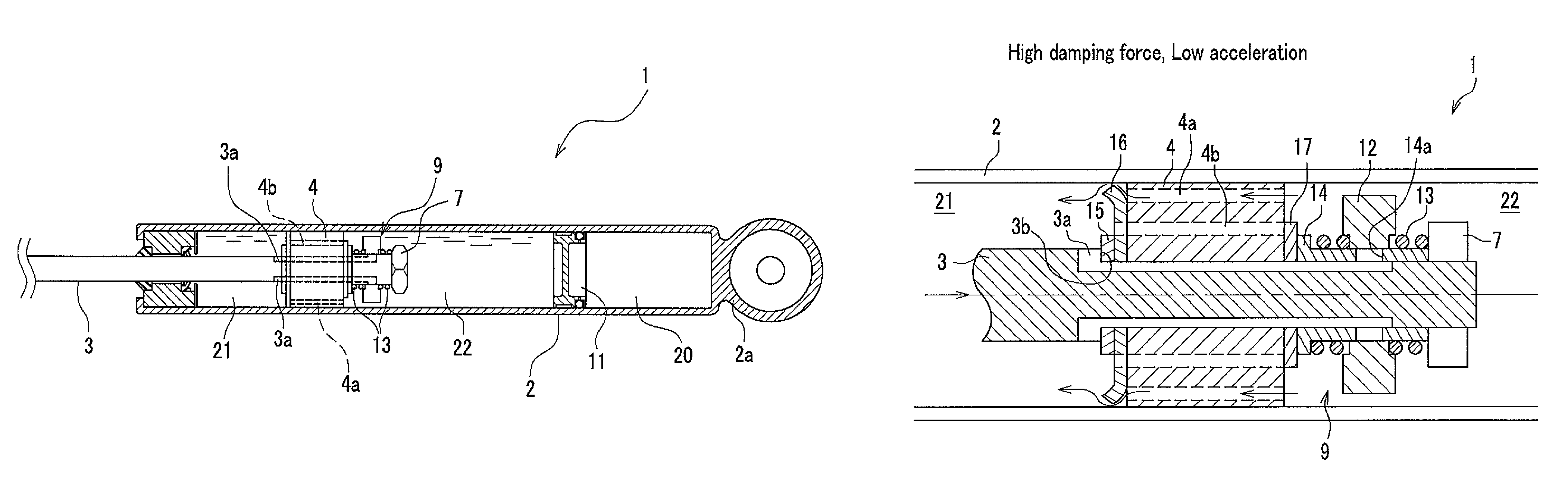
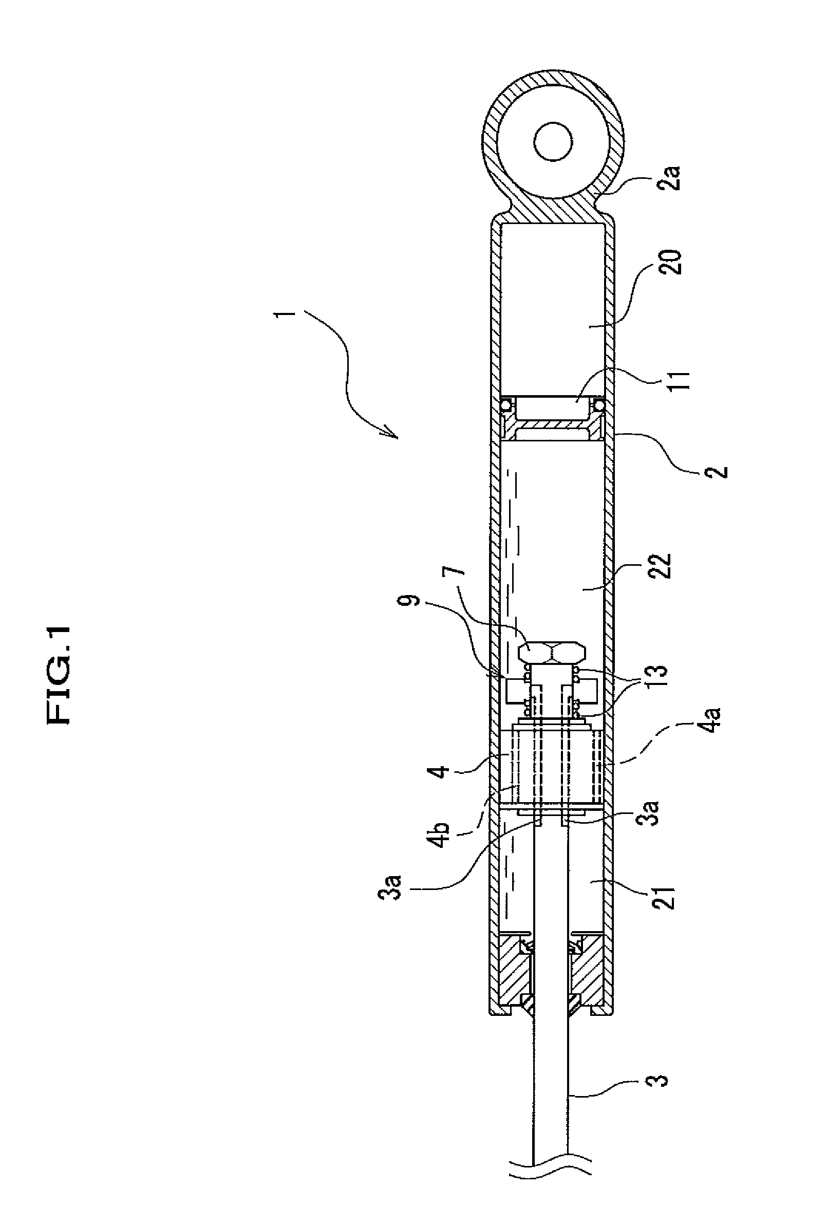
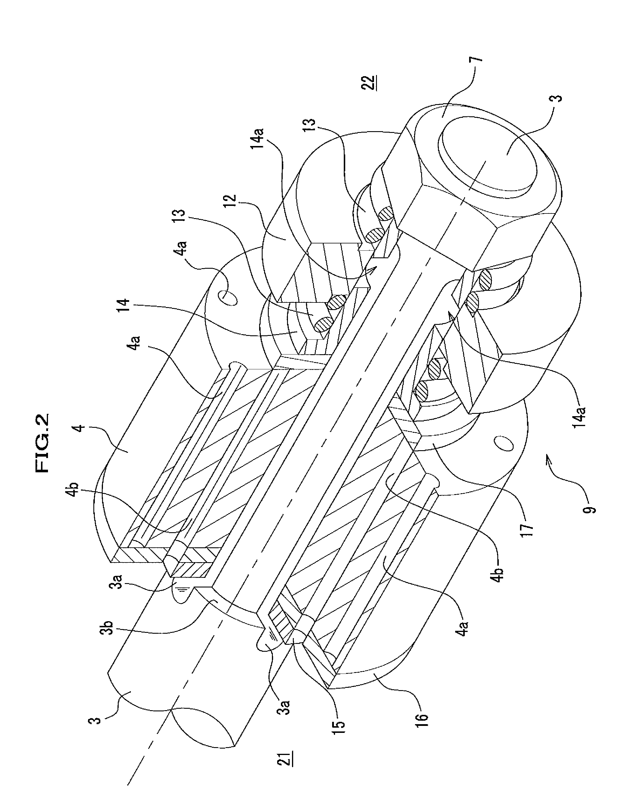
[0067]As shown in FIG. 1, a hydraulic shock absorber 1 is a so-called monotube type (de-Carbon) shock absorber, however, the present invention may also be applied to a twintube type shock absorber. The hydraulic shock absorber 1 includes a cylindrical cylinder 2 in which a fluid such as oil or MRF (Magneto-Rheological Fluid) is filled, a piston 4 which is slidably fitted into the cylinder 2 and partitions the cylinder 2 into a first fluid chamber 21 and a second fluid chamber 22, a piston rod 3 which is connected to a piston 4 and slidably penetrates through an end wall of the cylinder 2, an opening controlling unit 9 which is provided to the piston rod 3, a nut 7 for fixing the opening controlling unit 9 to the piston rod 3, and a free piston 11 which partitions the second fluid chamber 22 and a high pressure gas chamber 20.

[0068]The cylinder 2 includes an eye piece 2a at its end portion which is opposed to the end portion having a bore through which the piston rod 3 penetrates. If...

second embodiment

Modification of Second Embodiment

[0153]FIGS. 13A and 13B are illustrations showing operations of a hydraulic shock absorber according to a modification of the second embodiment of the present invention. FIG. 13A is an enlarged cross sectional view showing a main part of the hydraulic shock absorber in a case where an input load to the piston rod is small. FIG. 13B is an enlarged cross sectional view showing a main part of the hydraulic shock absorber in a case where an input load to the piston rod is large.

[0154]In the second embodiment, as an example of the second communication passage 3Aa which is formed on the piston rod 3A, groove like second communication passages 3Aa are described which are provided on the outer circumferential surface 3Ae of the smaller diameter portion 3Ac of the piston rod 3A as shown in FIGS. 7 and 8, however, the second communication passage 3Aa is not limited to these groove like second communication passages 3Aa.

[0155]As shown in FIGS. 13A and 13B, a se...

third embodiment

[0158]Next, a hydraulic shock absorber 1B according to a third embodiment of the present invention is described with reference to FIGS. 14 to 18. Components of the third embodiment corresponding to those of the first and second embodiments are assigned similar reference numerals, and descriptions thereof are omitted.

[0159]The hydraulic shock absorber 1B of the third embodiment shown in FIG. 14 is a vehicle suspension system in which a piston 4B is arranged at the lower end of a piston rod 3B such that the piston 4B is elastically movable along the piston rod 3B in up-down direction. The hydraulic shock absorber 1B is also provided with valve controlling units 5B (a first valve controlling unit 5B1 and a second valve controlling unit 5B2) for controlling the openings of the first leaf valve 41 and the second leaf valve 42.

[0160]As shown in FIGS. 15 and 16, the hydraulic shock absorber 1B includes a cylinder 2B, the piston rod 3B, the piston 4B, first communication passages 4Ba, third...


PUM


Abstract

A hydraulic shock absorber which includes a piston which is slidably fitted into a cylinder and partitions the cylinder into first and second fluid chambers; and a piston rod which is connected to the piston and slidably penetrates through an end wall of the cylinder, wherein the piston rod penetrates through the piston and includes on the outer circumferential surface of the piston rod at least one groove which communicates between the first and second fluid chambers, and the first and second fluid chambers are communicated with each other through the at least one groove.

Description

CROSS REFERENCE TO RELATED APPLICATIONS[0001]This application claims the foreign priority benefit under 35 U.S.C. §119 of Japanese Patent Application No. 2008-270649 filed on Oct. 21, 2008, Japanese Patent Application No. 2008-305318 filed on Nov. 28, 2008, Japanese Patent Application No. 2008-306301 filed on Dec. 1, 2008, Japanese Patent Application No. 2009-007495 filed on Jan. 16, 2009, and Japanese Patent Application No. 2009-027014 filed on Feb. 9, 2008, the disclosures of which are incorporated herein by reference.BACKGROUND OF THE INVENTION[0002]1. Field of the Invention[0003]The present invention relates to a hydraulic shock absorber for damping vibration.[0004]2. Description of the Related Arts[0005]A hydraulic shock absorber is used, for example, for damping vibrations of a vehicle body of a road vehicle. In the hydraulic shock absorber, a cylinder is partitioned into first and second fluid chambers with a piston, and a fluid flows between the first and second fluid chambe...

Claims


Application Information

Patent Timeline
Patent Type & Authority Patents(United States)
IPC IPC(8): F16F9/34
CPCF16F9/5126
Inventor AZEKATSU, YOSHITOMO
Owner HONDA MOTOR CO LTD
Why Eureka
Try Eureka