Lower structure of automotive vehicle

a technology for automotive vehicles and lower structures, applied in the direction of vehicle components, resilient suspensions, pivoted suspension arms, etc., can solve the problems of reduced support rigidity, deformation and breakage of control rings, and in the vehicle width direction of suspension cross members, so as to reduce collision load. the effect of load

Inactive Publication Date: 2013-07-23
MAZDA MOTOR CORP
View PDF17 Cites 45 Cited by
  • Summary
  • Abstract
  • Description
  • Claims
  • Application Information

AI Technical Summary

Benefits of technology

[0013]An object of the present invention is to provide a lower structure of an automotive vehicle which can secure the support rigidity of the suspension cross member during the normal vehicle traveling and also achieve the smooth retreat of the power unit to restrain the collision load from having bad influence on passengers in the vehicle frontal collision.

Problems solved by technology

However, since some kinds of vehicles have no rubber bush at the attachment portions, but both plate-shaped members having a high (great) rigidity are fastened directly by bolts, the suspension cross member could not be detached easily from the vehicle body.
In this structure, when a drive shaft hits against the arm portion so that a specified load acts on this arm portion in the vehicle frontal collision, the slit of the control ring easily causes deformation and breakage of the control ring.
However, in case the structure is constituted so that the suspension cross member can be detached easily from the vehicle body like the above-described conventional structures, there is a problem in that the support rigidity, in the vehicle width direction, of the suspension cross member during the normal vehicle traveling would be decreased.
Therefore, the above-described easy detachment of the suspension cross member from the bracket would improperly decrease the support rigidity, in the vehicle width direction, of the suspension cross member during the normal vehicle traveling.
Thereby, the conventional structures of the second and third patent documents would improperly decrease the support rigidity, in the vehicle width direction, of the suspension cross member during the normal vehicle traveling as well.

Method used


Image

  • Lower structure of automotive vehicle
  • Lower structure of automotive vehicle
  • Lower structure of automotive vehicle

Examples


embodiment 1

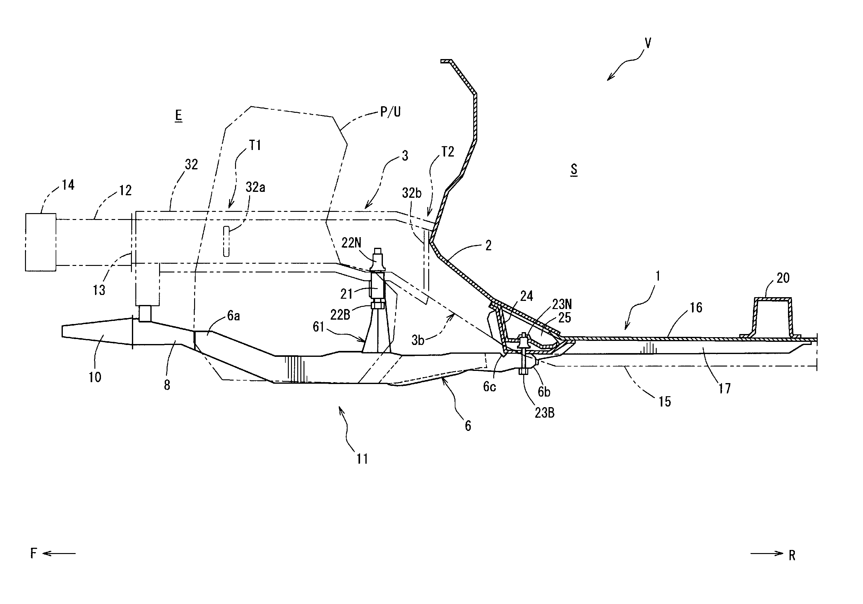
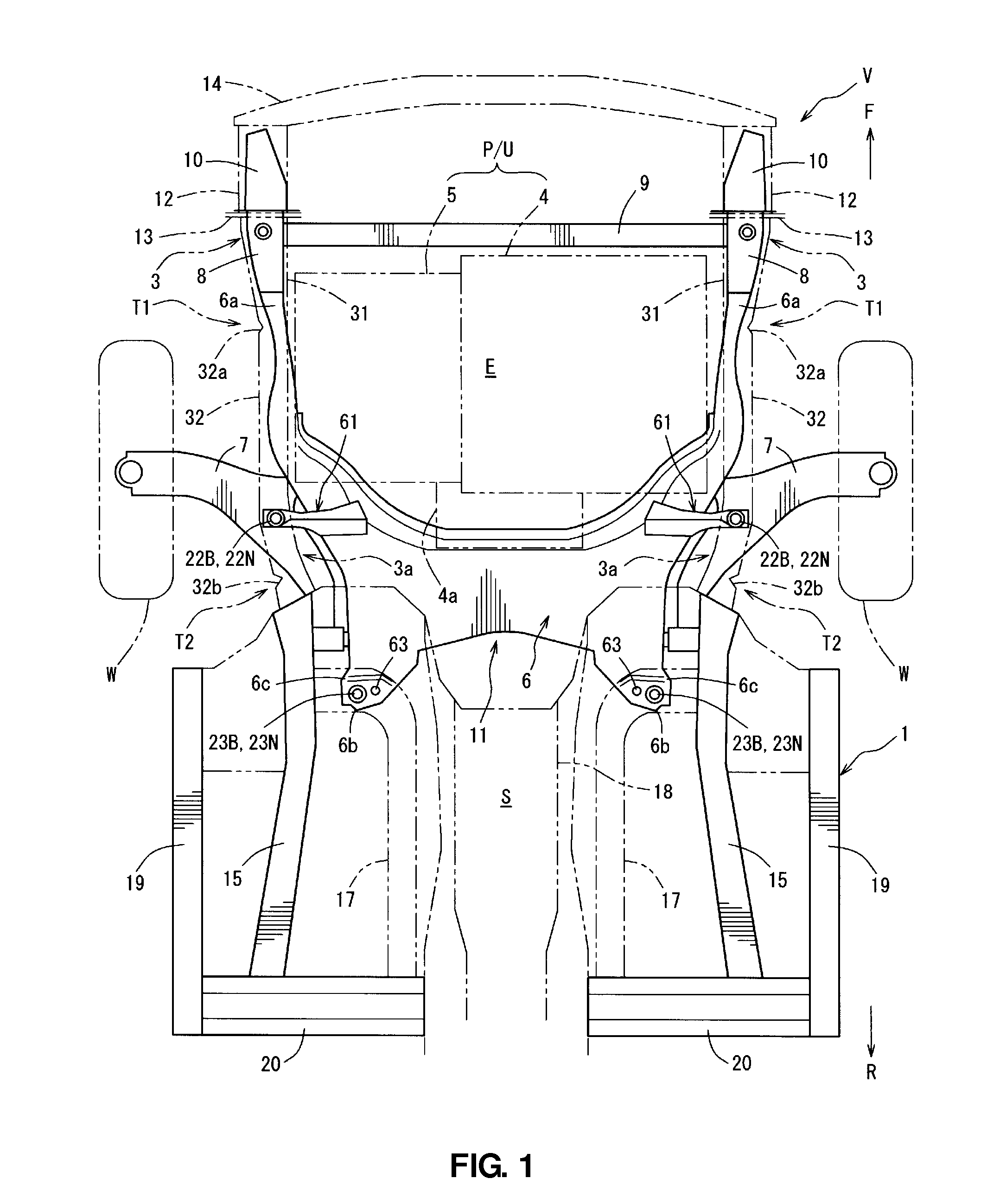
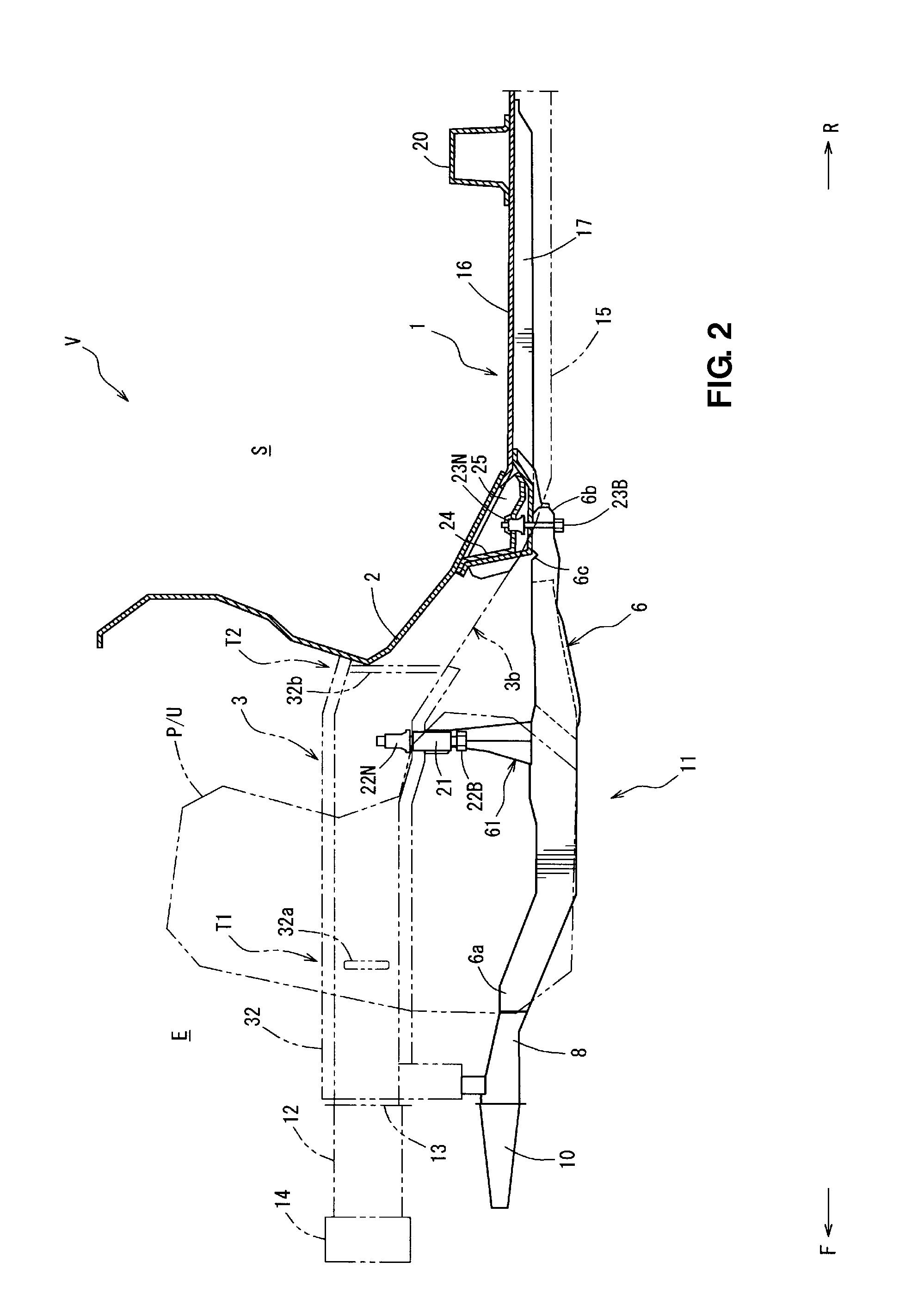
[0044]FIG. 1 is a plan view showing a lower structure of an automotive vehicle according to a first embodiment of the present invention, and FIG. 2 is a side sectional view showing the lower structure of an automotive vehicle. As shown in FIGS. 1 and 2, a vehicle body 1 of a vehicle V comprises a dash panel 2 (see FIG. 2) which partitions an engine room E from a vehicle room S and a pair of front side frames 3 which is provided in front of the dash panel 2. An arrow F shows a vehicle forward direction and an arrow R shows a vehicle rearward direction in the figures.

[0045]Between the pair of front side frames 3 is provided the engine room E, where a power unit P / U which comprises an engine 4, a transmission 5 and so on is arranged. Reference numeral 4a in FIG. 1 denotes an exhaust system of the engine 4. Herein, the present invention should not be limited to the vehicle equipped with the power unit P / U comprising the engine 4, but is applicable to any vehicle which is equipped with a...

embodiment 2

[0143]While the portion supporting the lower portion 21c of the pipe-shaped attaching member 21 is constituted by another member different from the front panel member 61B or the rear panel member 61C in the above-described embodiment first embodiment, the present invention should not be limited to this. For example, as shown by a middle-portion attaching member 71 in FIGS. 18 and 19, a lower support portion 71h which corresponds to the lower support member 61D may be formed integrally with a rear panel 71C. FIG. 18 is a perspective view showing the middle-portion attaching member 71 according to a second embodiment of the present invention. FIG. 19 is a sectional view taken along line E-E of FIG. 18. The same elements of the second embodiment as those of the above-described first embodiment are denoted by the same reference numerals, descriptions of which are omitted.

[0144]The middle-portion attaching member 71 is a vertical member which is comprised of a front panel member 71B and ...


PUM


Abstract

A suspension cross member comprises a middle-portion attaching member which extends upwardly from a suspension cross member body, and a pipe-shaped attaching member which is supported at a support portion provided at an upper portion of the middle-portion attaching member. A side portion, in a vehicle width direction, a front portion and a rear portion, in a vehicle longitudinal direction, of a side face portion of the attaching member are supported at the support portion. A lower portion of the attaching member is supported at the support portion with a specified support rigidity, in the vehicle longitudinal direction, which is lower than that of the supporting of the side portion, the front portion or the rear portion of the side face portion of the attaching member.

Description

BACKGROUND OF THE INVENTION[0001]The present invention relates to a lower structure of an automotive vehicle which comprises a pair of side frames which extends forwardly from a front portion of a vehicle room and a suspension cross member provided behind or below a power unit which is arranged between the pair of side frames and extends in a vehicle width direction.[0002]Many structures which can absorb the vehicle-collision energy properly so as to restrain the collision load from having bad influence on passengers in a vehicle room in the vehicle frontal collision or the like, by using retreat of a power unit arranged at a vehicle front portion, have been proposed.[0003]Generally, a suspension cross member supporting a suspension arm for a front vehicle is provided behind or below the power unit. Accordingly, a retreat of the power unit may be hindered by the suspension cross member.[0004]For this reason, according to conventional structures, the suspension cross member is forcib...

Claims


Application Information

Patent Timeline
Patent Type & Authority Patents(United States)
IPC IPC(8): B62D21/02
CPCB62D21/155B62D21/11
Inventor TAKESHITA, HIROAKIOTANI, TAKAHIROFUKUSHIMA, MASANOBU
Owner MAZDA MOTOR CORP
Why Eureka
Try Eureka