Pneumatic seat cushion system

a cushion bladder and pneumatic technology, applied in the field of seat cushions, can solve the problems that the manual operation system is not always suitable for many types of chairs, and achieve the effect of preventing the overexpansion of the self-inflating cushion bladder

Active Publication Date: 2013-08-20
JERVIS 17 PTY LTD
View PDF15 Cites 11 Cited by
  • Summary
  • Abstract
  • Description
  • Claims
  • Application Information

AI Technical Summary

Benefits of technology

[0012]Preferably, a valve is located in the tube between the self inflating cushion bladder and the displacement bladder, so as to prevent shock inflation of the displacement bladder and to make the transition towards equilibrium barely noticeable.
[0013]It is also preferred that a relief valve is inserted into the self inflating self inflating cushion bladder so as to prevent the overexpansion of the self inflating cushion bladder in the event of a rise in the differential air pressure between the inside and the outside of the self inflating cushion bladder.

Problems solved by technology

However, a manually operated system is not always suitable for use in many types of chairs as found in reception areas, conference centres, auditoriums, meeting rooms and transport, where the sitter may not be aware of the existence or benefits of a manually operated valve system or its method of operation.

Method used


Image

  • Pneumatic seat cushion system
  • Pneumatic seat cushion system
  • Pneumatic seat cushion system

Examples


Embodiment Construction

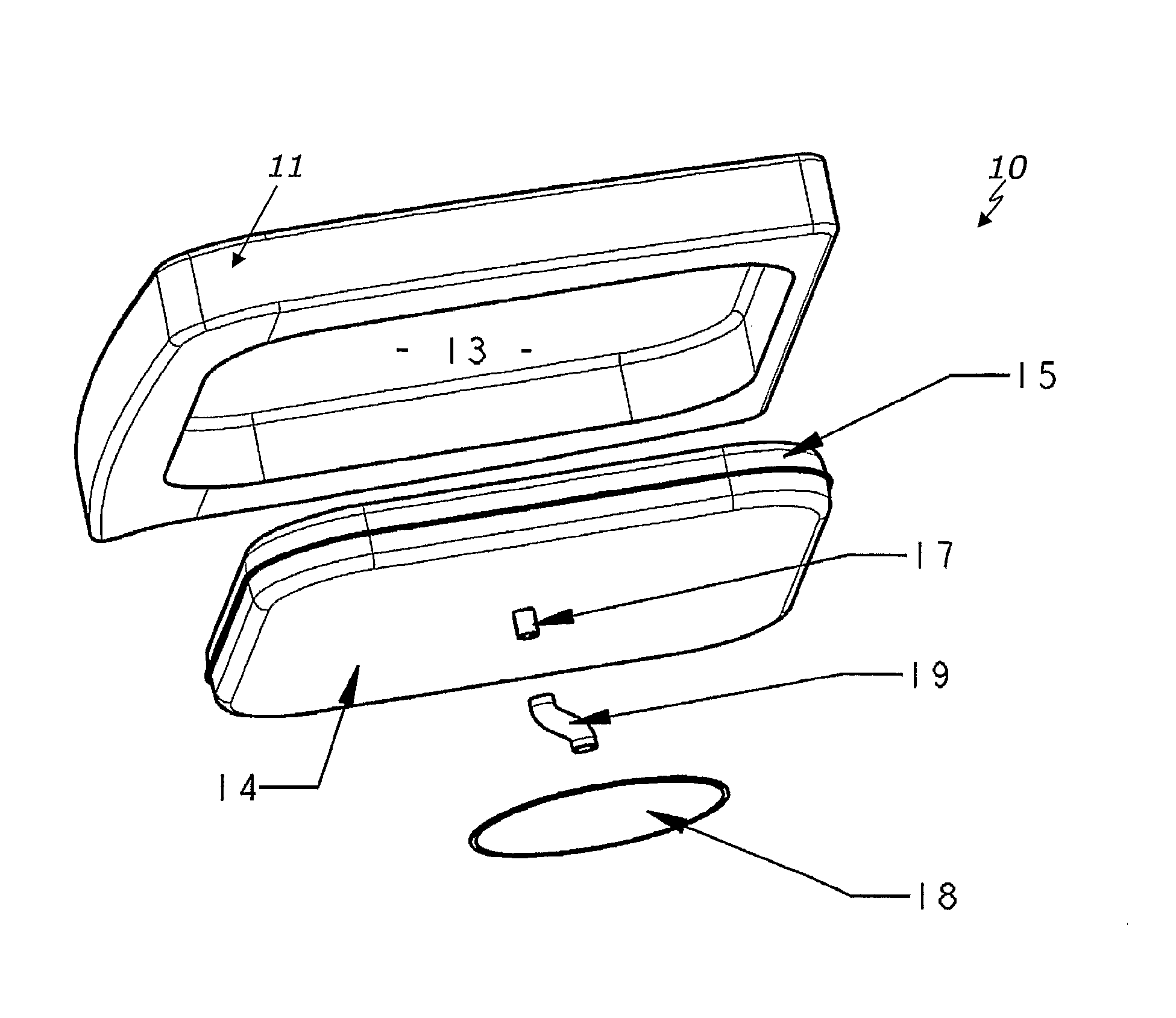
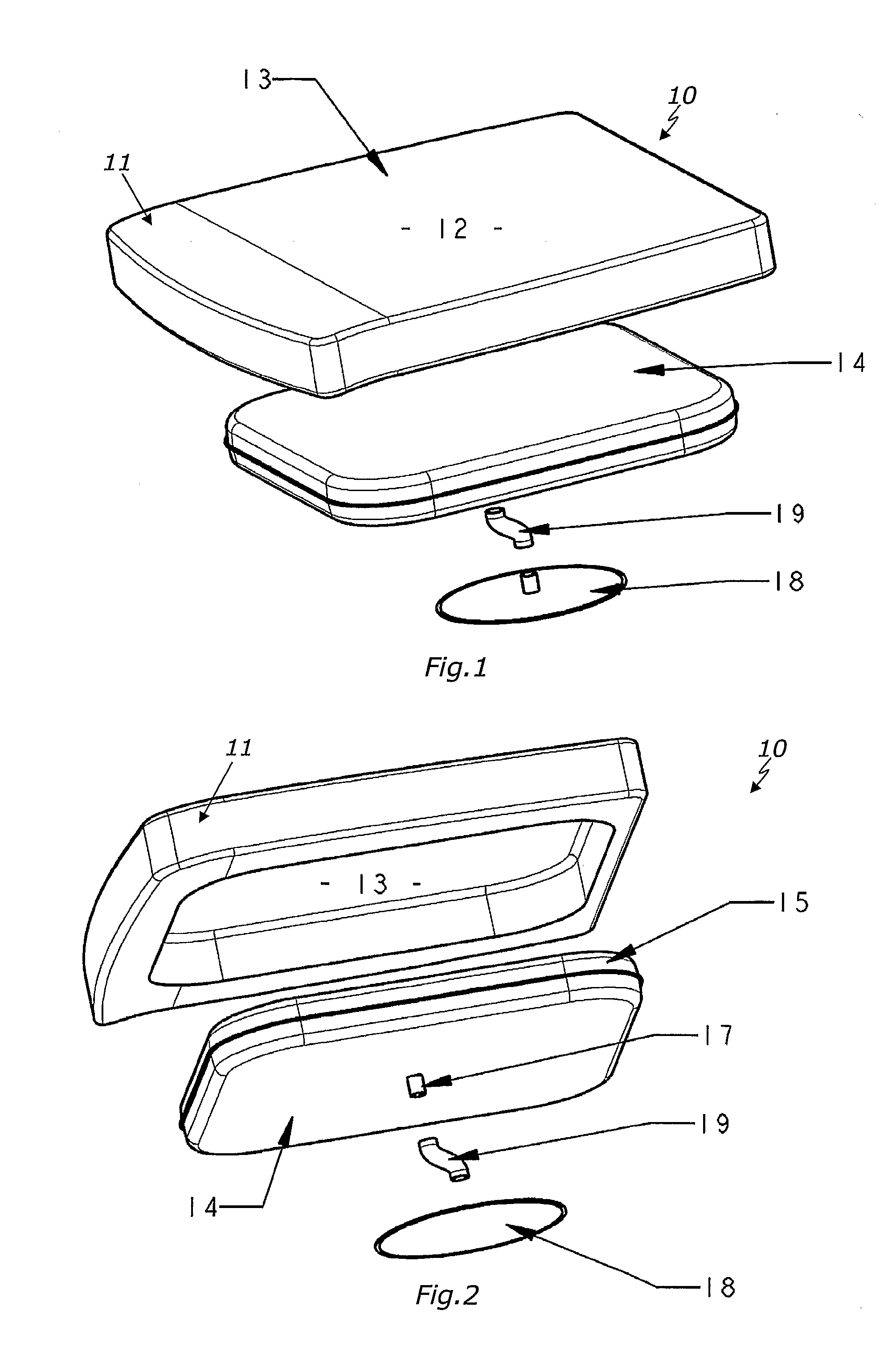
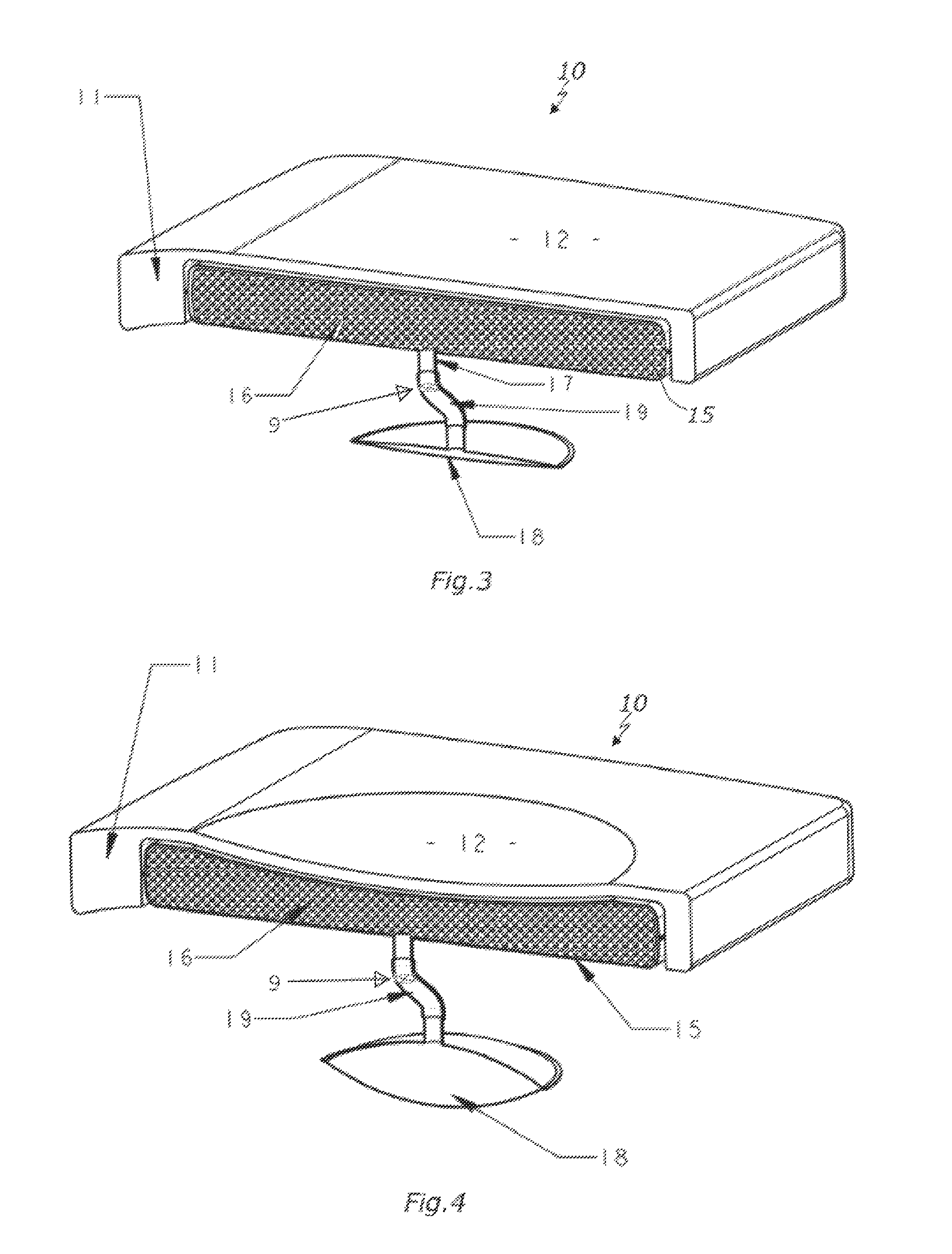
[0039]As depicted in FIGS. 1, 2 and 3, the pneumatic seat cushion system 10 shown in the drawings consists of a foam cushion 11 with upholstery that has a seating surface 12 and a recess 13 in its underside. Within the recess 13 and adjacent to the seating surface 12 there is a self inflating cushion bladder 14 which consists of an airtight envelope 15 that contains compressible material 16 including, as an example, an open cell foam. Air enters and leaves the airtight envelope 15 through a port 17 that is connected to a displacement bladder 18 by a connecting tube 19 so as to form a closed system.

[0040]When the seat cushion system is not in use, the self inflating cushion bladder 14 is fully inflated and the displacement bladder 18 is deflated as shown in FIGS. 1, 2 and 3. When a person sits on the seating surface 12, the compressible material is compressed and air is displaced from the self inflating cushion bladder into the displacement bladder 18 via the port 17 and tube 19 unti...


PUM


Abstract

A pneumatic seat cushion system (10) has a deformable cushion (11) having a seating surface (12) and a self inflating cushion bladder (14) positioned beneath the seating surface (12). The self inflating cushion bladder (14) has an airtight envelope (15) containing compressible material (16) which is in air communication (19) with a displacement bladder (18) such that when in use the airtight envelope (15) and the displacement bladder (18) form a closed system from which no air can enter or escape. When there is no person seated on the seating surface (12), the self inflating cushion bladder (14) is inflated and the displacement bladder (18) is deflated. When there is a person seated on the seating surface, the weight of the person compresses the compressible material (16) so as to partially deflate the self inflating cushion bladder (14) which results in the contained air passing into the displacement bladder (18) which becomes fully inflated.

Description

TECHNICAL FIELD[0001]This invention relates to seat cushions and more particularly to a pneumatic seat cushion system that automatically moulds to individual body shapes and provides postural support and comfort.BACKGROUND ART[0002]Existing self inflating adjustable seat cushions are designed to mould exactly to individual body shapes and provide postural support and comfort with the use of manually operated mechanical and electrical valve systems. Manually operated systems allow individual adjustment, particularly where a chair is frequently used by the same person. However, a manually operated system is not always suitable for use in many types of chairs as found in reception areas, conference centres, auditoriums, meeting rooms and transport, where the sitter may not be aware of the existence or benefits of a manually operated valve system or its method of operation. Furthermore, it would be preferable for the self inflating seat cushion to reinflate (reset) after the chair is va...

Claims


Application Information

Patent Timeline
Patent Type & Authority Patents(United States)
IPC IPC(8): B68G5/00A47C16/00
CPCA47C4/54A47C27/084A47C27/088A47C7/14B60N2/7088A47C7/02B60N2/7082A47C7/142
Inventor LEE, RALPH EDWARD
Owner JERVIS 17 PTY LTD
Why Eureka
Try Eureka