Clip connection

a technology of screw connection and screw hole, which is applied in the direction of furniture, lighting and heating equipment, walls, etc., can solve the problems of affecting the appearance of the grid, adversely affecting the feel of the joint to the installer, and affecting the fit of the standard cross tee connector, etc., to achieve uniform effective thickness, improve the fit and improve the effect of standardized cross tee connectors

Inactive Publication Date: 2013-08-20
USG INTERIORS INC
View PDF7 Cites 6 Cited by
  • Summary
  • Abstract
  • Description
  • Claims
  • Application Information

AI Technical Summary

Benefits of technology

[0004]The invention improves the fit of standardized cross tee connectors when received in slots of tees with different gauge thickness for various duty ratings and / or spans. The invention involves the concept of producing grid tees with a range of service duty, reflected in the use of various gauge sheet stock, that exhibit an effective uniform thickness at their cross tee slots. More specifically, the invention comprehends locally altering a grid tee in the area of its cross tee receiving slot or slots so that the grid tee has a uniform effective thickness at these area(s) that can be standardized across a manufacturer's range of tee load ratings.
[0005]In a preferred embodiment, a grid tee is permanently stamped with an indentation or dimple adjacent the cross tee slot and the connector has a lead edge area arranged to seat against the bottom of the indentation. The bottom of the indentation of tees made of different gauge thickness are formed with the same spacing from the center plane of the tee. Since the connector registers against it, this indentation bottom surface serves to establish the effective thickness of the slotted tee and in accordance with the invention a tee has the same dimension regardless of the actual gauge of material forming the tee. Ideally, the indentation is laterally offset, with reference to a view of the side of the tee, from the center of the slot so that the material displaced from the indentation for one connector does not substantially affect a similarly offset indentation for an opposing connector on the opposite side of the tee.

Problems solved by technology

A problem can exist where the same cross tee connector is used for all of a manufacturer's slotted tees.
A lighter gauge slotted tee will have a tendency to be loose in the fit provided for it by a cross tee connector.
This looseness adversely affects the feel of the joint to the installer and can potentially affect the appearance of the grid as well as the manner in which other components of the ceiling are received and / or are supported by the grid.

Method used


Image

  • Clip connection
  • Clip connection
  • Clip connection

Examples


Embodiment Construction

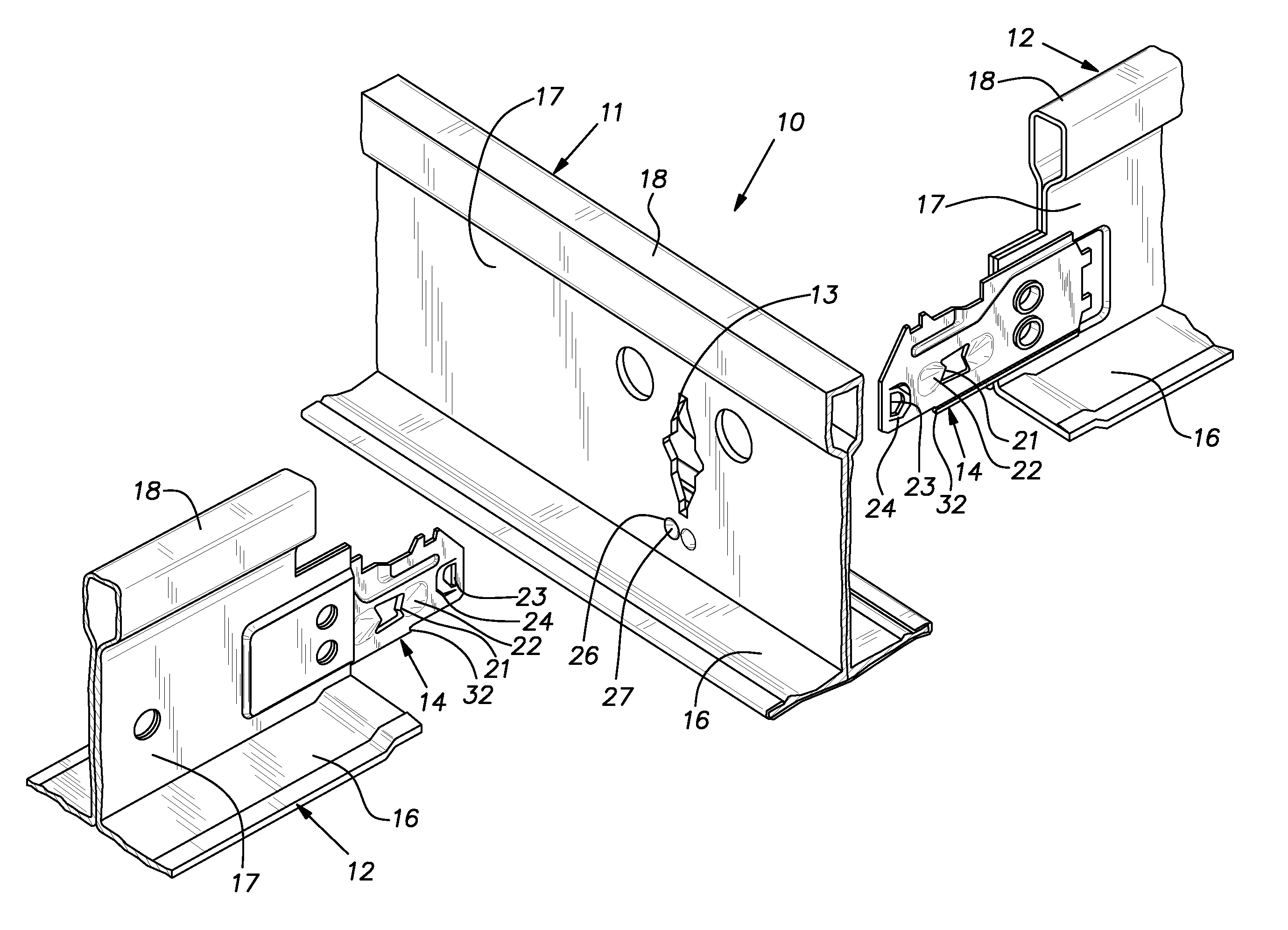
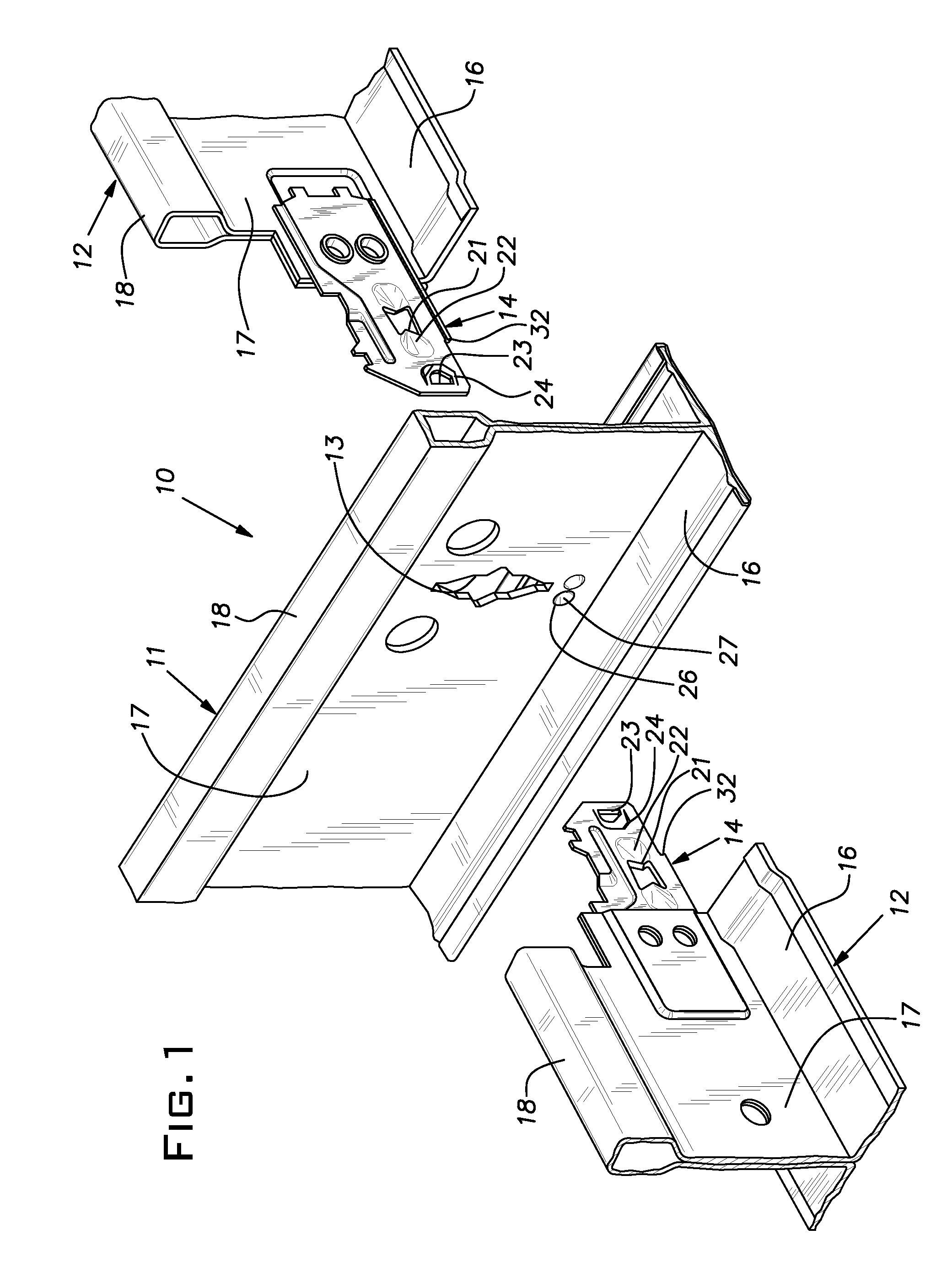
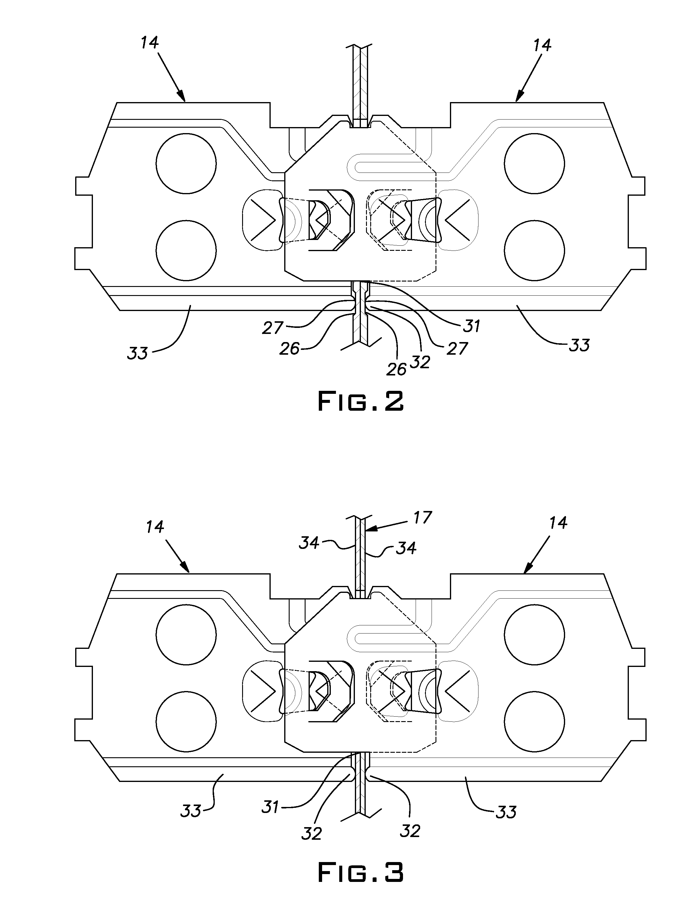
[0011]Referring now to the figures, there is shown a small section of a suspended ceiling grid 10 at an intersection of tees 11, 12 (exploded in FIG. 1 for clarity). A slotted tee or runner 11 represents a main tee, which typically is 10 or 12′ in length (or metric equivalent) or a shorter cross tee. A main tee will have numerous regularly spaced identical slots 13 while a cross tee will have relatively few slots 13 or no slots at all. In various views herein, two opposed cross tees 12 intersect the slotted tee 11 at the slot 13. The cross tees 12 are assembled with end connectors 14 that, in a known manner, lock together when they are both properly inserted in a slot 13. U.S. Pat. Nos. 5,517,796 and 5,761,868, incorporated herein by reference, disclose the general features of the end connector or clip 14. While not shown, but known in the industry, the cross tees 12 can have slots and be intersected by still other cross tees in the grid of the ceiling.

[0012]The tees 11, 12 are typi...


PUM


Abstract

Producing grid tees with a range of service duty, reflected in the use of various gauge sheet stock, that exhibit an effective uniform thickness at their cross tee slots by locally altering a grid tee in the area of its cross tee receiving slot or slots so that the grid tee has a uniform effective thickness at these area(s) that can be standardized across a manufacturer's range of tee load ratings. Preferably, a grid tee is permanently stamped with an indentation or dimple adjacent the cross tee slot and a cross tee connector has a lead edge area arranged to seat against the bottom of the indentation.

Description

BACKGROUND OF THE INVENTION[0001]The invention relates to suspended ceilings and, in particular, to improvements in tee components used to construct a metal grid for such ceilings.PRIOR ART[0002]Suspended ceilings usually comprise a rectangular grid formed by spaced parallel main runners or tees and cross runners or tees extending perpendicularly between the main runners. The cross tees typically have end connectors that mate with identical connectors of other cross tees being joined end-to-end. The cross tee joints are made in a slot provided in the main tees. Where small grid modules are used in a ceiling construction, the cross tees can also be slotted to receive end connectors of other cross tees. Grid tees are typically made of roll-formed metal sheet stock and the gauge of the sheet stock is varied so that a tee is of adequate strength for the service it is expected to fulfill but, for costs reasons, not excessive. Also for reasons of economy, a manufacturer typically only use...

Claims


Application Information

Patent Timeline
Patent Type & Authority Patents(United States)
IPC IPC(8): F27D1/00
CPCE04B9/122
Inventor LEHANE, JR., JAMES J.
Owner USG INTERIORS INC
Why Eureka
Try Eureka