Open hole non-rotating sleeve and assembly

a non-rotating, open-hole technology, applied in the direction of drilling pipes, drilling/well accessories, directional drilling, etc., can solve the problems of increasing the torque at the surface, affecting the efficiency of drilling, so as to reduce the sliding and rotating torque

Active Publication Date: 2013-08-20
WWT NORTH AMERICA HLDG
View PDF50 Cites 19 Cited by
  • Summary
  • Abstract
  • Description
  • Claims
  • Application Information

AI Technical Summary

Benefits of technology

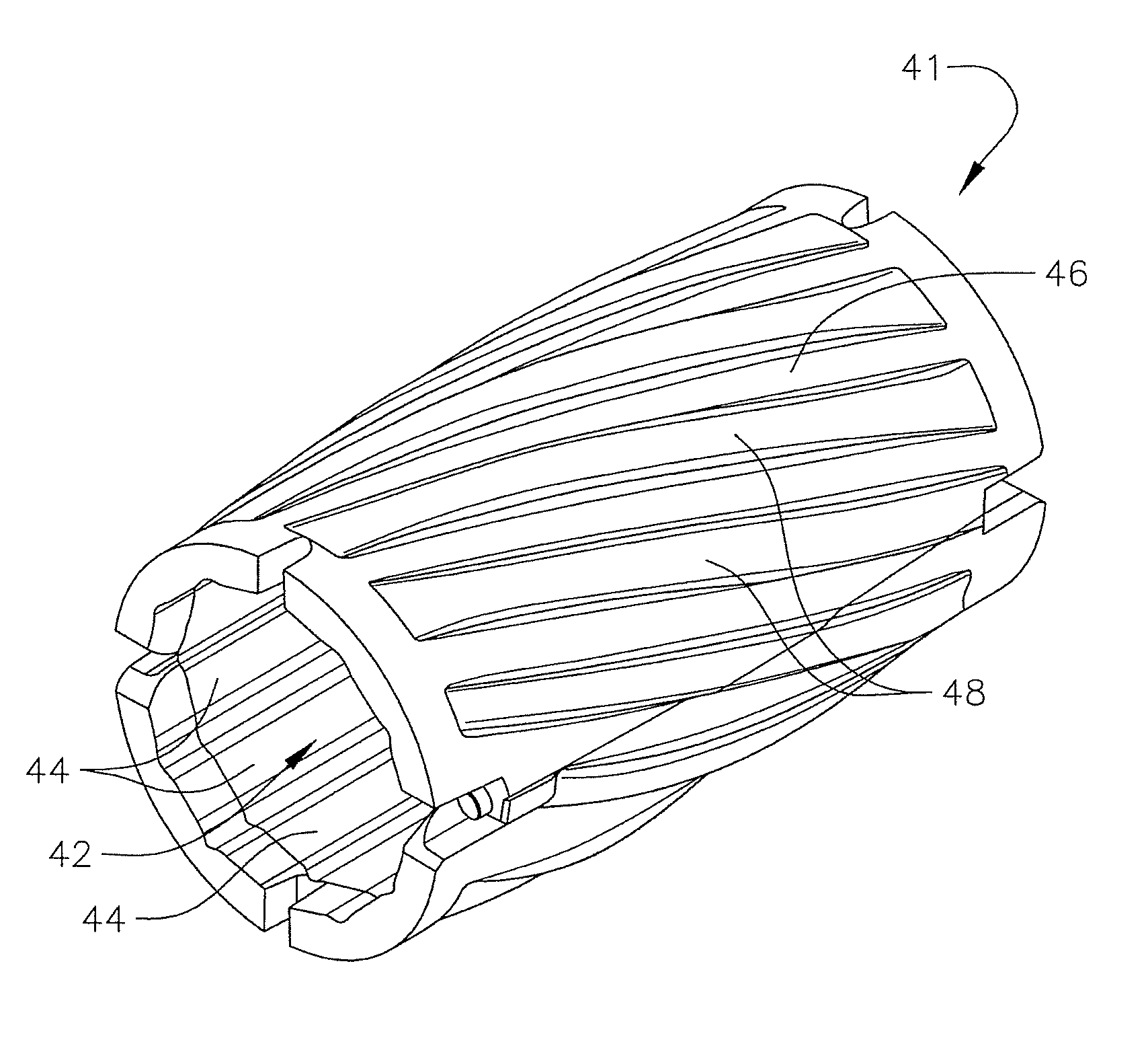
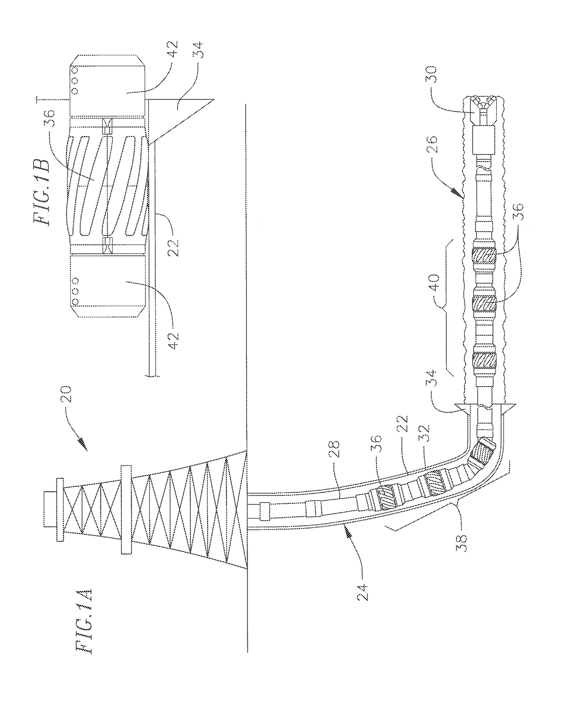
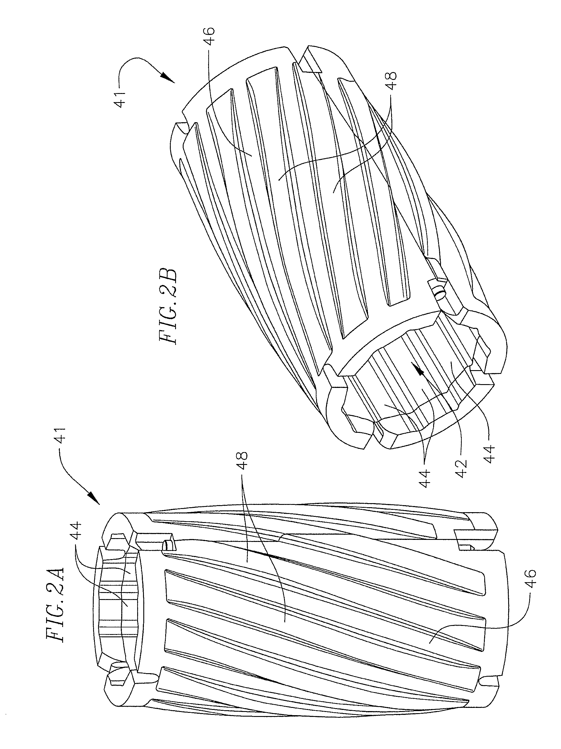
[0026]Briefly, one embodiment of the invention comprises a non-rotating downhole sleeve adapted for open hole drilling and / or casing centralization. The sleeve includes a tubular body made of hard plastic with integrally formed helical blades positioned around its outer surface. An inner surface of the sleeve allows drilling fluid circulation to form a non-rotating fluid bearing between the sleeve and the drill pipe or casing. The non-rotating sleeve construction reduces sliding and rotating torque while drilling, with minimal obstruction to drilling fluid or cement passing through the borehole between the helical blades.

Problems solved by technology

Casing centralizers have been used in the past, but with limited success.
Each of these centralizers has significant deficiencies.
'275 teaches a centralizer that has a clearance fit around the casing; but clearance fits result in contact bearing surfaces which produce coefficients of friction of 0.3 for typical plastics, resulting in significantly greater torque at the surface.
Charlton '267 teaches a tubular centralizer sleeve of unitary construction with a clearance fit and ID grooves that taper in depth longitudinally, also non-optimum, because it does not produce or allow a low friction bearing surface that reduces torque at the surface.
In summary, the current art for casing centralizers used for drilling, or for simply running casing, do not entirely address the combined issues of high torque, high sliding friction, resistance to damage when running over obstacles, and maximizing fluid flow past the centralizer.

Method used


Image

  • Open hole non-rotating sleeve and assembly
  • Open hole non-rotating sleeve and assembly
  • Open hole non-rotating sleeve and assembly

Examples


example

[0142]Performance testing was conducted with a test fixture that simulates performance in downhole environments. Testing conducted with the test fixture compared performance of the sleeve of this invention with a prior art drill pipe protector sleeve. Performance testing also was compared between the invention and a drill pipe tool joint operated in the absence of a drill pipe protector sleeve.

[0143]The test fixture tested performance of a sleeve on a drill pipe that rotated in a casing filled with mud while sliding downhole with specified side loads, with the drill pipe rotating at 120 rpm. A cement liner was used to simulate friction that develops in an open hole drilling environment.

[0144]Sliding COF (when sliding and rotating) and rotating COF (when sliding and rotating) were measured to compare performance (torque and drag reduction) of a sleeve corresponding to this invention (referred to as US-500) with a prior art drill pipe protector sleeve (referred to as SS-500). Test con...


PUM


Abstract

A non-rotating downhole sleeve adapted for open hole drilling and / or casing centralization. The sleeve includes a tubular body made of hard plastic with integrally formed helical blades positioned around its outer surface and an inner surface configuration which allows drilling fluid circulation to form a non-rotating fluid bearing between the sleeve and the drill pipe or casing. The helical blades reduce sliding and rotating torque while drilling, with minimal obstruction to drilling fluid passing through the borehole between the blades.

Description

CROSS-REFERENCE TO RELATED APPLICATIONS[0001]This application claims priority to U.S. Provisional Application No. 61 / 281,184, filed Nov. 13, 2009, and 61 / 340,062, filed Mar. 11, 2010, which are incorporated herein in their entirety.FIELD OF THE INVENTION[0002]This invention relates to gas and oil production, and more particularly, to improvements in open hole drilling with drill pipe and in casing centralization. Both drilling applications are improved upon by the present invention's use of specially designed non-rotating drill pipe protectors applied to the rotating drill pipe or casing.BACKGROUND[0003](a) Open Hole Non-Rotating Drill Pipe Protector:[0004]Recently new drilling and fracturing technology has allowed unconventional development for gas and oil production. Examples of major field developments include the Baaken play in North Dakota, the Marcellus play of Pennsylvania, and the Haynesville play of east Texas and Louisiana. These huge development opportunities have spawned...

Claims


Application Information

Patent Timeline
Patent Type & Authority Patents(United States)
IPC IPC(8): E21B17/18E21B21/12
CPCE21B17/1042E21B17/1078E21B17/1057
Inventor CASASSA, GARRETT C.MITCHELL, SARAH B.MOORE, NORMAN BRUCE
Owner WWT NORTH AMERICA HLDG
Why Eureka
Try Eureka