Method and circuit arrangement for controlling a load

a technology of circuit arrangement and load, applied in the direction of light sources, lighting devices, instruments, etc., can solve problems such as voltage variation, and achieve the effect of saving energy

Active Publication Date: 2013-08-20
LEAR CORP GMBH
View PDF11 Cites 5 Cited by
  • Summary
  • Abstract
  • Description
  • Claims
  • Application Information

AI Technical Summary

Benefits of technology

[0009]The object of the present invention is to provide a method and a device that handle this problem and, in a special embodiment, point out a possibility for saving energy during the discharge of the output capacitance.

Problems solved by technology

Problematic in the known state of the art, however, is the fact that there exist various control possibilities for electrical loads consisting of individual point loads or partial loads, especially LEDs.
Problematic above all in this case is that the voltage varies as a function of the number of controlled and connected point loads or partial loads.

Method used


Image

  • Method and circuit arrangement for controlling a load
  • Method and circuit arrangement for controlling a load
  • Method and circuit arrangement for controlling a load

Examples


Embodiment Construction

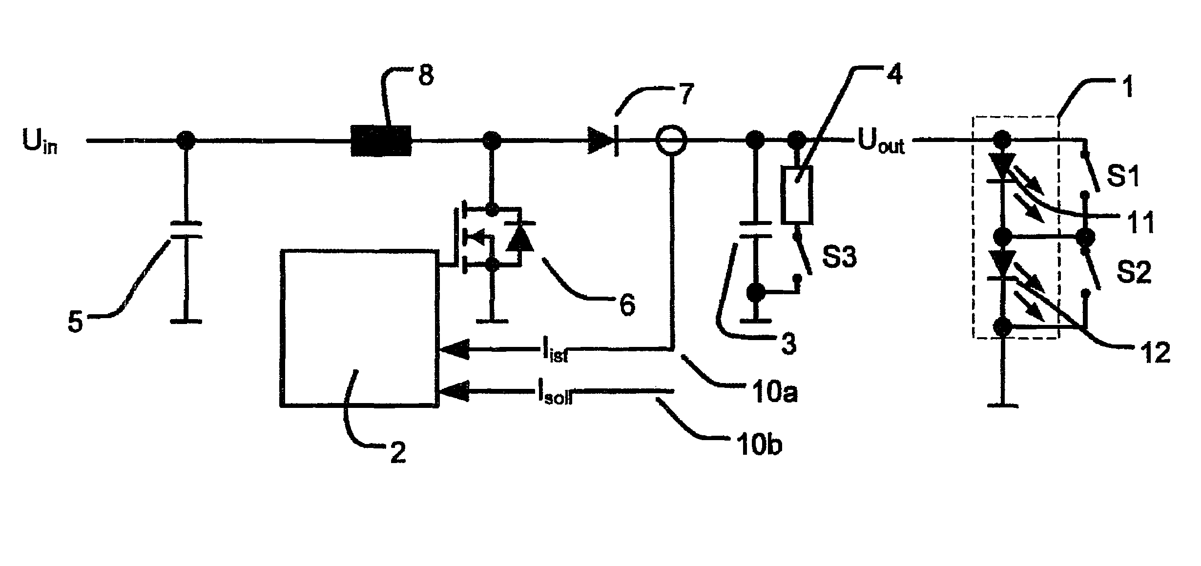
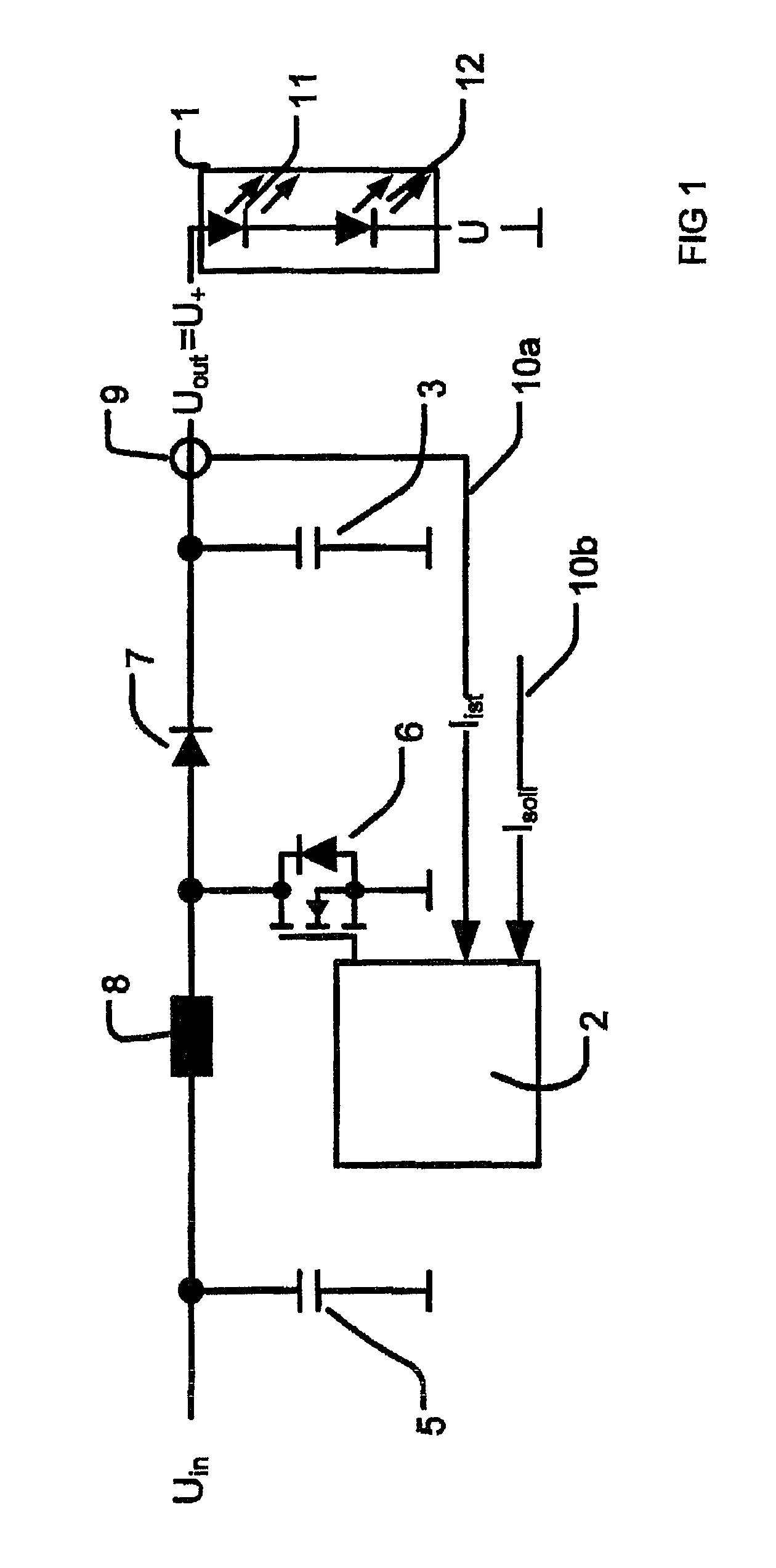
[0053]In the following description of the figures, the same reference characters for identical elements in the figures will be used for all of the figures. This will provide clarity and better understanding of the following concrete description of the invention based on FIG. 1 to FIG. 13.

[0054]FIG. 1 depicts a wiring of an electrical load 1 with a step-up converter. The electrical load 1 consists of at least two point loads 11, 12. The point loads 11, 12 each relate to at least one light-emitting diode. Although FIG. 1 represents only two light-emitting diodes connected in series, a nearly arbitrary number of light-emitting diodes can nevertheless be added. In an advantageous manner, it relates to at least two diodes connected in series and / or parallel which are connected as a diode array. But the diode array can also consist of a series connection and / or parallel circuit and / or matrix connection of individual light-emitting diodes.

[0055]The electrical load 1 is driven by a current ...


PUM


Abstract

A method for control and discharge control of an electrical load, in which the control and discharge occurs by means of a control frame and a discharge frame, and in which one control frame and one discharge frame represent one switching cycle for the electrical load. A plurality of switching cycles are arranged following one another, wherein a controllable switch is connected in parallel to each point load so that each point load can be switched independently of the other point load during the switching cycle. A control unit monitors the electrical current flowing in the electrical load, and the control unit uses an actual / setpoint comparison to control the current to an adjustable setpoint so that a current that is as constant as possible flows into the electrical load. The controllable switches switch on the point loads during the control frame of a switching cycle, and the controllable switches switch off the point loads during the discharge frame of a switching cycle.

Description

BACKGROUND OF THE INVENTION[0001]The present invention relates to a method and circuit arrangement for controlling an electrical load. The controlled electrical load particularly relates to an arrangement of light-emitting diodes, hereinafter called LEDs, wherein the electrical load is to be supplied with a nearly constant operating current.[0002]Constant-current sources are primarily used to control an electrical load, especially a load of LEDs, LED chains and / or LED arrays. Diverse arrangements of LEDs are known; besides parallel and matrix connection of LEDs, the possibility of series connection of LEDs is known. In a series connection of LEDs, all LEDs are connected behind one another in a row; this connection is also called an LED chain. In order to operate LED chains, a constant current is generated and conducted through the LEDs. A voltage that corresponds to the sum of the forward voltages of all LEDs then appears across the LEDs.[0003]To achieve a constant luminous efficacy...

Claims


Application Information

Patent Timeline
Patent Type & Authority Patents(United States)
IPC IPC(8): H05B37/02
CPCH05B33/0815H05B33/083H05B45/38H05B45/48
Inventor GREBNER, KLAUS-DIETER
Owner LEAR CORP GMBH
Why Eureka
Try Eureka