Electronic device

a technology of electronic devices and expansion cards, applied in the direction of electrical apparatus construction details, electrical apparatus casings/cabinets/drawers, instruments, etc., can solve the problems of inconvenient user and inability to use for securing expansion cards with a different length

Inactive Publication Date: 2013-08-20
HONG FU JIN PRECISION IND (SHENZHEN) CO LTD +1
View PDF29 Cites 14 Cited by
  • Summary
  • Abstract
  • Description
  • Claims
  • Application Information

AI Technical Summary

Benefits of technology

[0004]At present, some electronic devices, such as computers and servers, usually have a number of expansion cards, such as Peripheral Component Interconnect (PCI) cards, used therein. Typically, an electronic device includes a motherboard, a riser card connected to the motherboard, and a number of expansion cards connected to the riser card. In order that the expansion cards can connect to the riser card stably, a securing structure is usually used for securing the expansion cards. However, a conventional securing structure only can be used for securing expansion cards with certain length, and cannot be used for securing an expansion card with a different length. Therefore, when a user of the electronic device want to change an expansion card in the electronic device for an expansion card with different length, the securing structure also should be changed, this is inconvenient to the user.

Problems solved by technology

However, a conventional securing structure only can be used for securing expansion cards with certain length, and cannot be used for securing an expansion card with a different length.
Therefore, when a user of the electronic device want to change an expansion card in the electronic device for an expansion card with different length, the securing structure also should be changed, this is inconvenient to the user.

Method used


Image

  • Electronic device
  • Electronic device
  • Electronic device

Examples


Embodiment Construction

[0010]Embodiments of the present disclosure will now be described in detail below, with reference to the accompanying drawing.

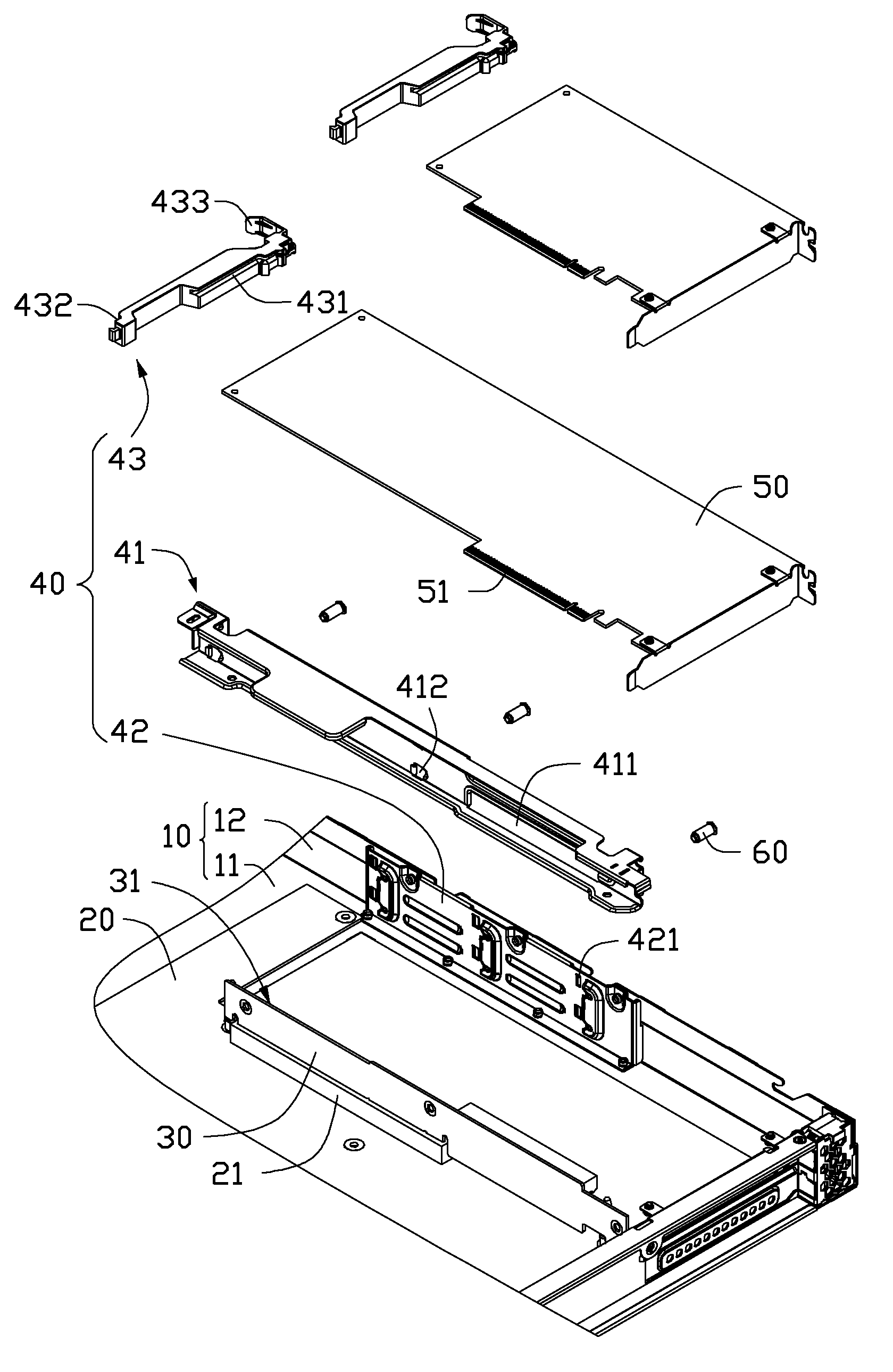
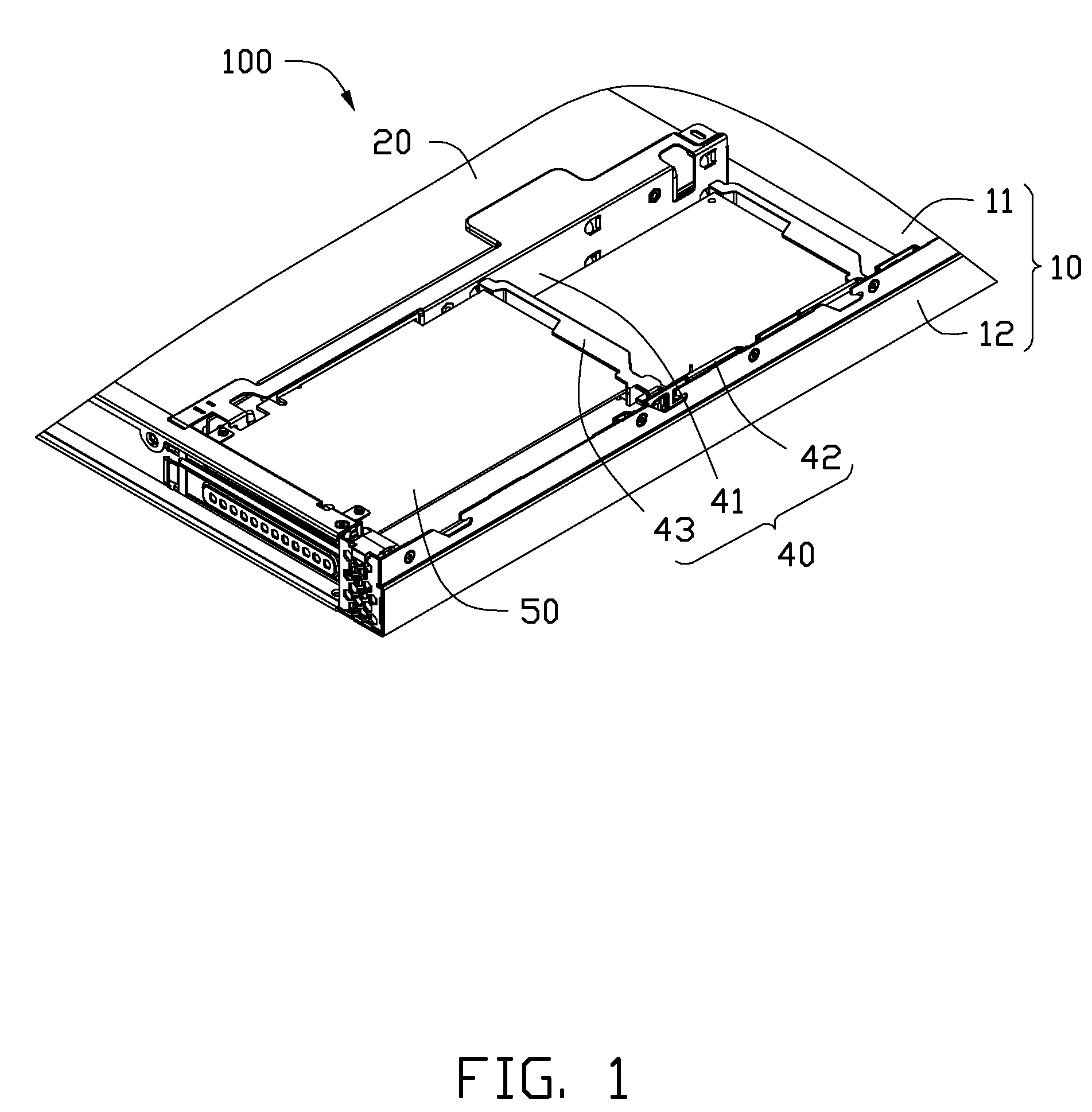
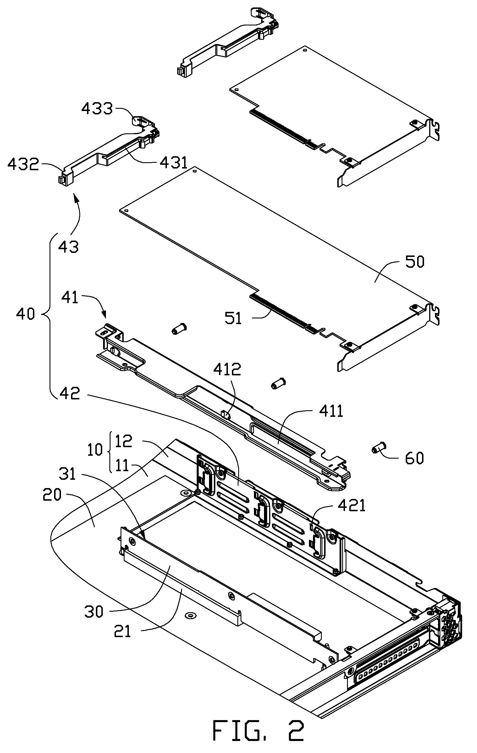
[0011]Referring to FIGS. 1 to 3, an electronic device 100 according to an exemplary embodiment is shown. The electronic device 100 includes a housing 10, a motherboard 20, a riser card 30, a securing structure 40 and at least one expansion card 50. The electronic device 100 can be a computer or a server. The number of the expansion card(s) 50 in the electronic device 100 can be one, two, three, or more.

[0012]The housing 10 includes a bottom plate 11 and a lateral plate 12 connected to the bottom plate 11. In the present embodiment, the lateral plate 12 is substantially perpendicular to the bottom plate 11. The motherboard 20 is fixed to the bottom plate 11. The motherboard 20 is a central printed circuit board (PCB) of the electronic device 100.

[0013]The riser card 30 is a plug-in card, and can be plugged into a first socket 21 of the motherboard 20. The rise...


PUM


Abstract

An electronic device includes a motherboard, a riser card, and a securing structure. The riser card connects to the motherboard, and includes a first surface with a second socket thereon for connecting with an expansion card. The securing structure is for securing the expansion card, and includes a first fixing plate, a second fixing plate, and a fixing member for fixing the expansion card. The first fixing plate is arranged on the first surface of the riser card, and includes a number of first latching portions corresponding to the second socket, the first latching portions are arranged on a line parallel to the second socket. The second fixing plate faces the first surface of the riser card, and includes a second latching portion corresponding to each first latching portion. The fixing member includes a first and second end portion latchable with each first and second latching portion respectively.

Description

BACKGROUND[0001]1. Technical Field[0002]The present disclosure relates to electronic devices and, particularly, to an electronic device with a securing structure for securing expansion cards.[0003]2. Description of Related Art[0004]At present, some electronic devices, such as computers and servers, usually have a number of expansion cards, such as Peripheral Component Interconnect (PCI) cards, used therein. Typically, an electronic device includes a motherboard, a riser card connected to the motherboard, and a number of expansion cards connected to the riser card. In order that the expansion cards can connect to the riser card stably, a securing structure is usually used for securing the expansion cards. However, a conventional securing structure only can be used for securing expansion cards with certain length, and cannot be used for securing an expansion card with a different length. Therefore, when a user of the electronic device want to change an expansion card in the electronic...

Claims


Application Information

Patent Timeline
Patent Type & Authority Patents(United States)
IPC IPC(8): H05K7/14
CPCH05K5/0269
Inventor ZHANG, GUANG-YIZHANG, ZHE
Owner HONG FU JIN PRECISION IND (SHENZHEN) CO LTD
Why Eureka
Try Eureka