Developing device and image forming apparatus

a technology of developing device and image forming apparatus, which is applied in the direction of electrographic process apparatus, instruments, optics, etc., can solve the problems of inability to maintain image density at a desired level, adverse effects on image density, and unstable image quality, so as to maintain constant the quantity of the developer supplied to the developer supply par

Inactive Publication Date: 2013-08-20
RICOH KK
View PDF27 Cites 0 Cited by
  • Summary
  • Abstract
  • Description
  • Claims
  • Application Information

AI Technical Summary

Benefits of technology

[0041]According to the above-described features, a developer extraction port is provided on the side of the developer inlet port receiving the developer from the reservoir, and defines the quantity of developer to be introduced in the developer supply part of the developing device. Accordingly, a constant quantity of developer is supplied to the developer supply part. The developer extraction port is connected to the reservoir, and the developer collecting part of the developing device is also connected to the reservoir. Accordingly, an excess quantity of developer over the defined quantity required for the developer supply part is collected in the reservoir. Even if the quantity of developer varies according to changes in the environmental conditions, the quantity of the developer supplied to the developer supply part is maintained constant. This arrangement can prevent abnormal image reproduction due to shortage of the developer or dispersing of the particles due to excessive supply of the developer.

Problems solved by technology

If electrification is insufficient, the image density is adversely affected and the image quality is likely to be unstable.
Especially if the electrification level is less than a predetermined level, the image density cannot be maintained at a desired level.
In addition, toner particles are suspended and attached to the background surface of the photoreceptor, which phenomenon is called background contamination.
Thus the feeding quantity of the developer cannot be maintained constant.
Still another problem caused by use of a screw or a rotary feeder is that an air gap is generally provided between the inner wall of the housing and the screw or the rotary feeder.
For this reason, the sealing characteristic may be insufficient, and this may cause the feeding quantity to be inconsistant.
Air-current feeding of the developer may be desirable compared with use of a screw; however, it is difficult for the air-current feeding method to check the actual quantity of the developer being fed in the developing device, especially the quantity of the developer fed to the developer supply port although a rotary feeder is able to define a quantity of feeding.
If the quantity of developer supplied to the developing device is short of a required quantity, the image density become unstable.

Method used


Image

  • Developing device and image forming apparatus
  • Developing device and image forming apparatus
  • Developing device and image forming apparatus

Examples


Embodiment Construction

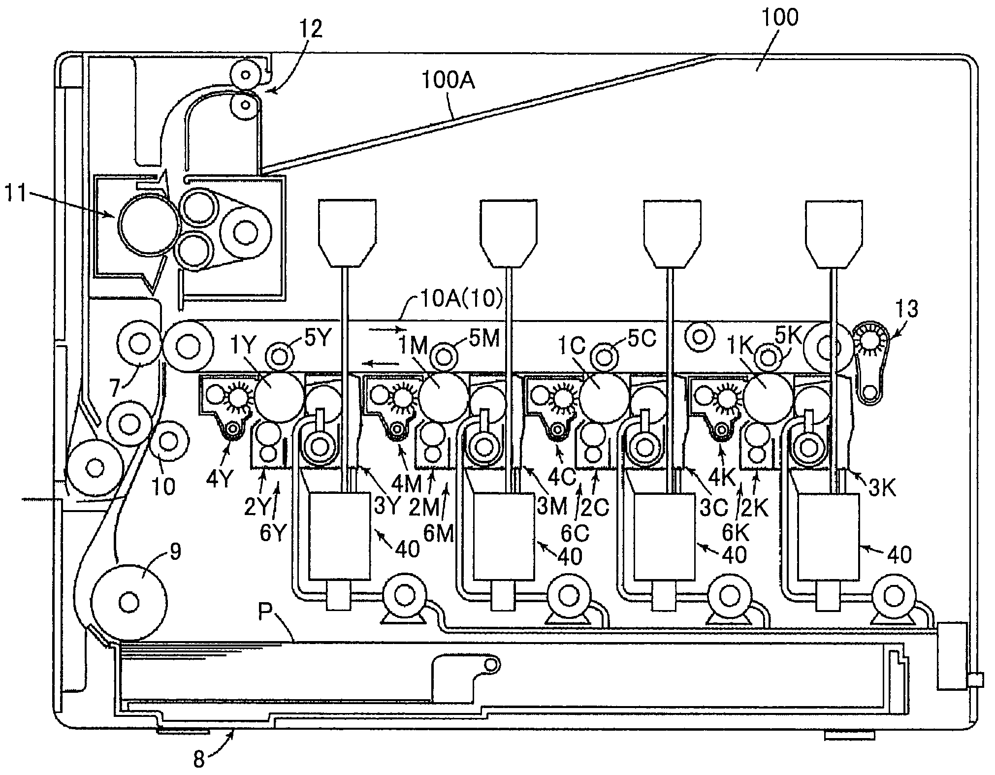
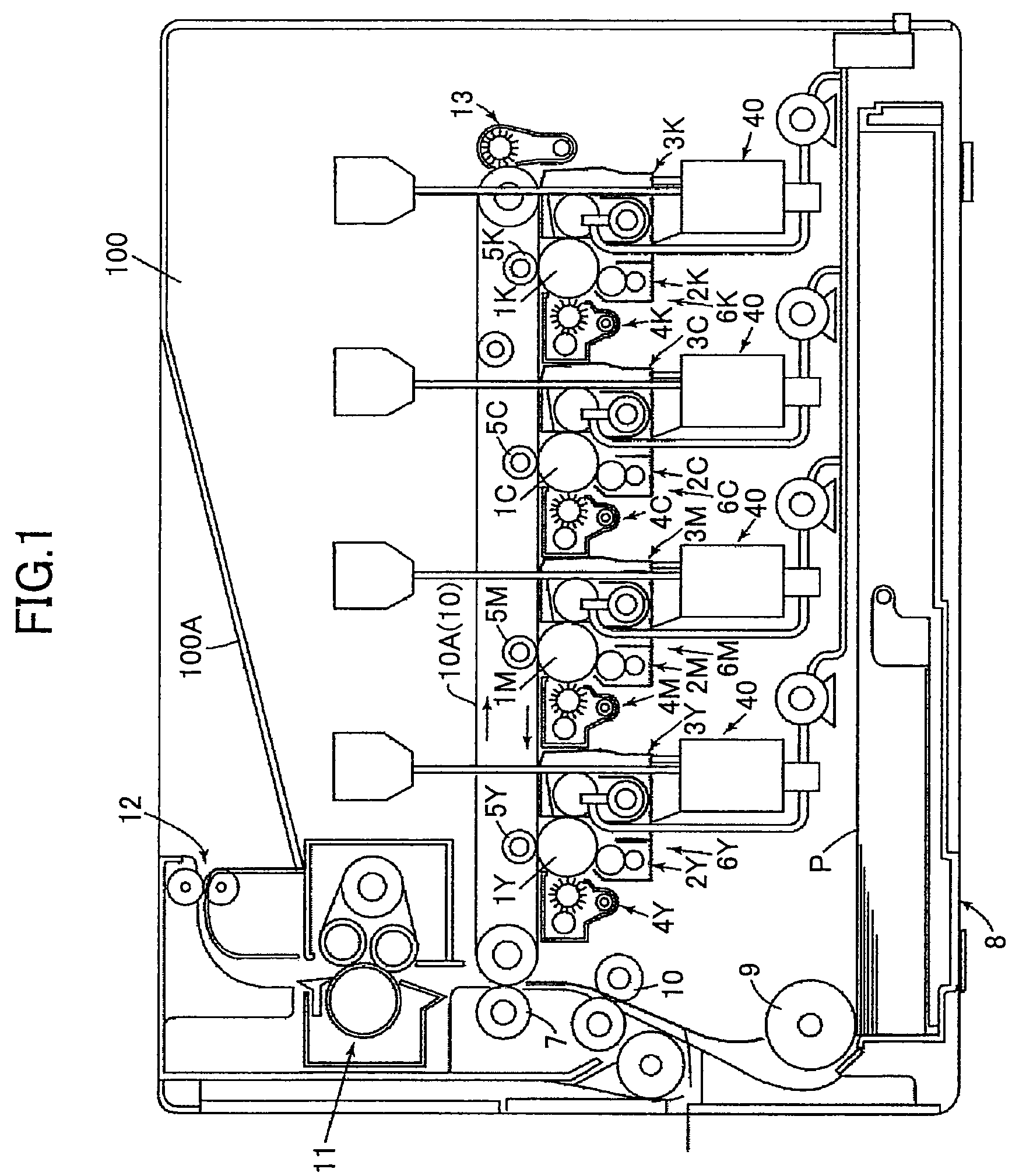
[0053]The preferred embodiments of the present invention will now be described below in conjunction with the attached drawings. FIG. 1 is a schematic diagram of an image forming apparatus using a developing device according to an embodiment of the invention. The image forming apparatus shown in FIG. 1 is, for example, a tandem-type full-color printer. However, the invention is not limited to this example and it is applicable to many other image forming apparatuses including copy machines and facsimile machines.

[0054]The image forming apparatus shown in FIG. 1 has four image creating units 6Y, 6M, 6C and 6K for creating color images of yellow (Y), magenta (M), cyan (C) and black (K), respectively, which units are arranged under an intermediate transfer unit 10 so as to face the bottom face of an intermediate transfer belt 10A that carries unfixed images in a body frame 100 of the image forming apparatus.

[0055]The image creating units 6Y, 6M, 6C and 6K have the same structure except t...


PUM


Abstract

A developing device includes a developer supply part and a developer collecting part, wherein the developer supply part has a developer inlet port for introducing a developer supplied from a reservoir into the developer supply part and a developer extraction port provided on the side of the developer inlet port to remove a portion of the developer so as to define a quantity of the developer to be introduced in the developer supply part, and wherein the developer extraction port and the developer collecting part are connected to the reservoir.

Description

TECHNICAL FIELD[0001]The present invention generally relates to a developing device and an image forming apparatus, and more particularly, to a circulating mechanism for a two-component (binary system) developer.BACKGROUND ART[0002]In an image forming apparatus, such as a copy machine, a facsimile machine or a printing machine, an electrostatic latent image is formed by a light on a photoreceptor and the electrostatic latent image is developed into a toner image by a developing device. Then the toner image is transferred as a visualized image onto a sheet so as to output recorded information.[0003]There are two types of developer used in the development process. One is magnetic or nonmagnetic single-component developer and the other is two-component (binary system) developer containing toner and carrier for carrying toner particles. When these components are mixed, toner particles are electrically charged due to frictional electrification caused by the stirring / mixture process and b...

Claims


Application Information

Patent Timeline
Patent Type & Authority Patents(United States)
IPC IPC(8): G03G15/08
CPCG03G15/0822G03G2215/0827G03G2215/0822
Inventor MATSUMOTO, JUNICHIOHMURA, TOMOYAMATSUE, NATSUMITAKUMA, YASUOKIKUCHI, HIROSHI
Owner RICOH KK
Why Eureka
Try Eureka