Removable tooth cap and method of attachment therefor
- Summary
- Abstract
- Description
- Claims
- Application Information
AI Technical Summary
Benefits of technology
Problems solved by technology
Method used
Image
Examples
Embodiment Construction
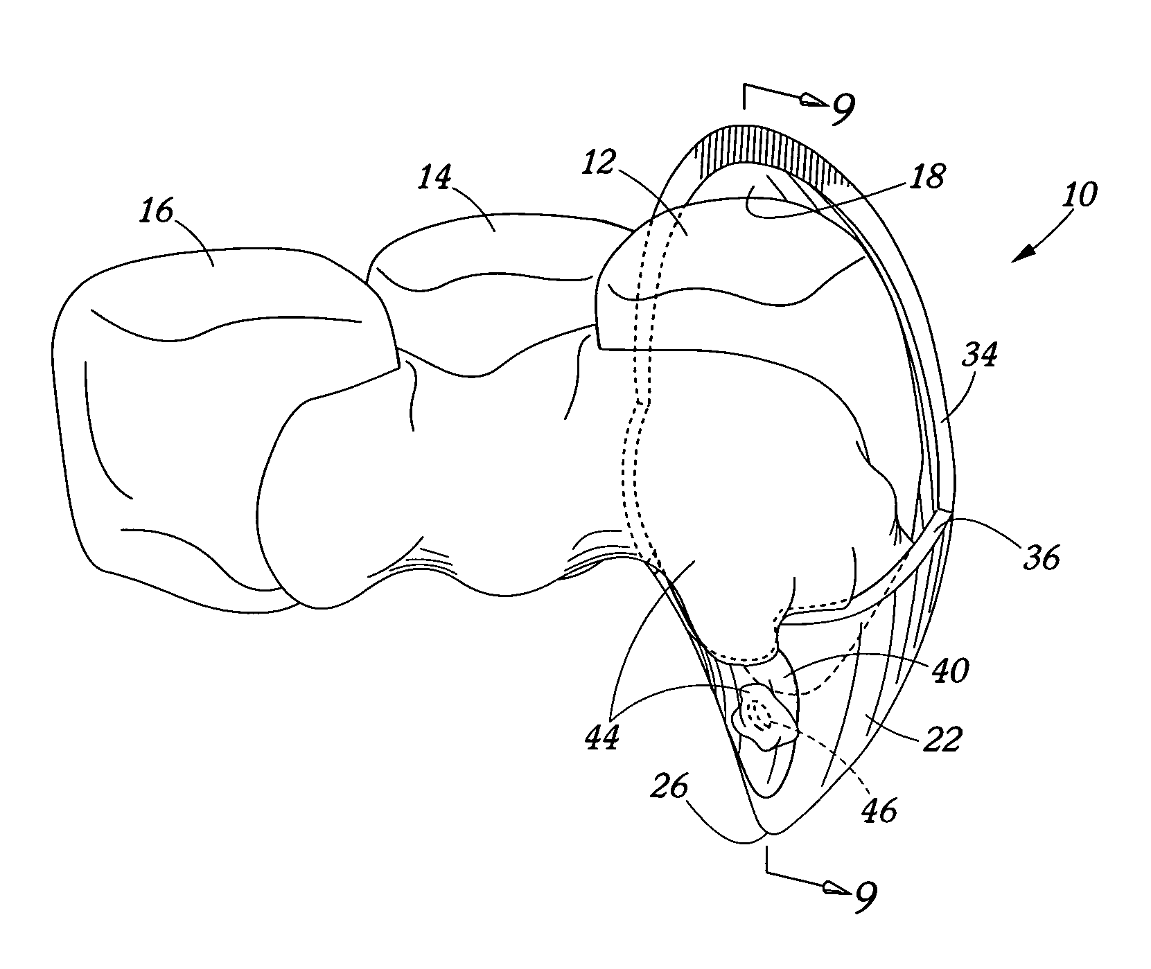
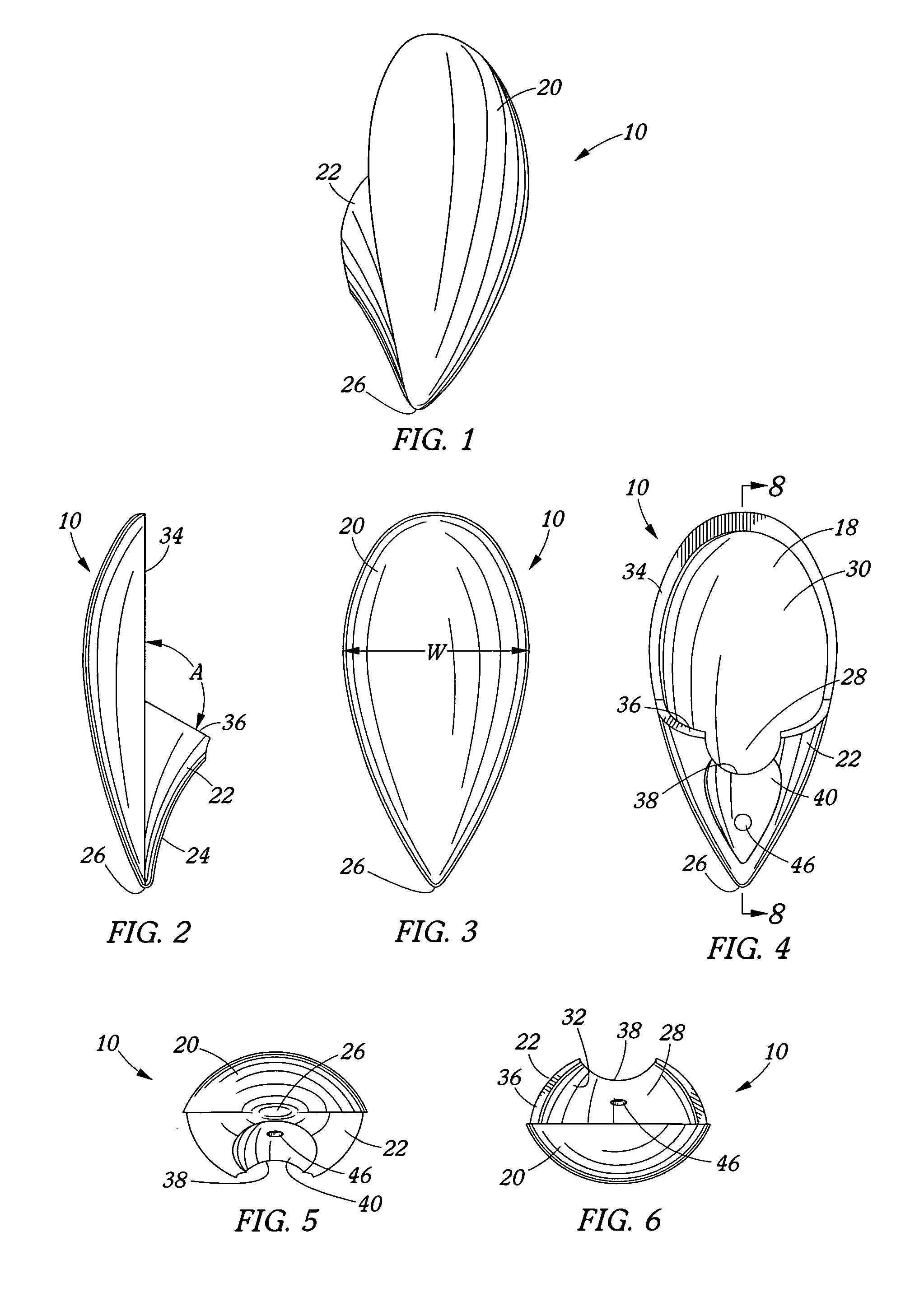
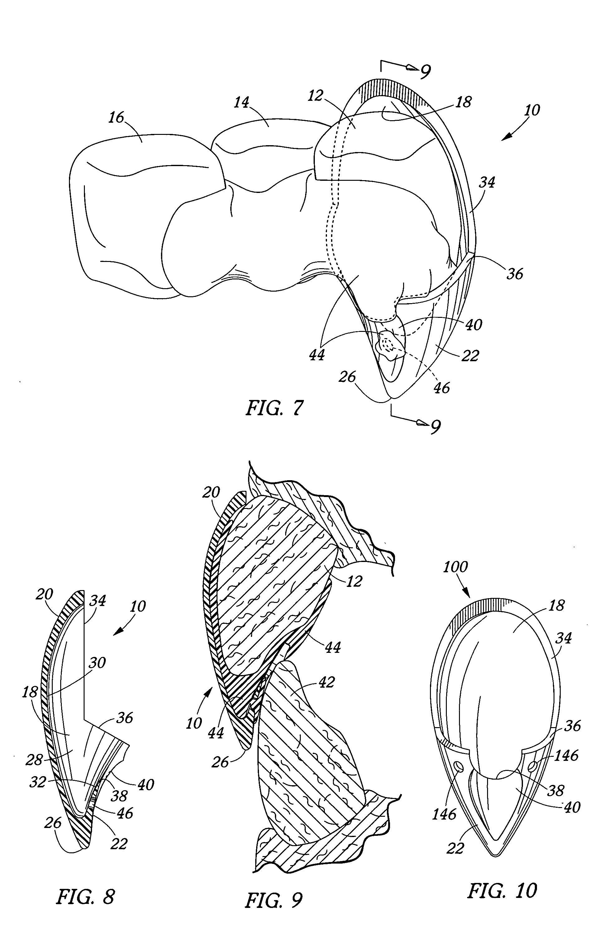
[0027]Turning now to the drawings, FIGS. 1 through 6 illustrate the tooth cap 10 of the present invention in isolation. FIG. 7 shows tooth cap 10 mounted or positioned on an individual's left upper canine tooth 12. While shown on a canine tooth, the tooth cap could be mounted on any other canine tooth, an incisor tooth, or any other tooth capable of being received in the cavity 18 of the tooth cap. As also shown, tooth cap 10 includes a generally convex shaped front side 20 and back side 22 which converge together to form an extension 24, a tip 26, and a trough 28 of the tooth cap's cavity 18. As perhaps best shown in FIG. 8, cavity 18 is defined by generally concave shaped inside surfaces 30, 32 of the tooth cap's front and back sides 20, 22, respectively. As also shown, the concave shaped inside surface 30 of front side 20 terminates at a generally flat peripheral edge or rim 34 while the inside surface 32 of the back side 22 terminates at an edge 36 referred to as back edge 36 wh...
PUM
 Abstract
Description
Claims
Application Information
 - R&D
- Intellectual Property
- Life Sciences
- Materials
- Tech Scout
- Unparalleled Data Quality
- Higher Quality Content
- 60% Fewer Hallucinations
Browse by: Latest US Patents, China's latest patents, Technical Efficacy Thesaurus, Application Domain, Technology Topic, Popular Technical Reports.
© 2025 PatSnap. All rights reserved.Legal|Privacy policy|Modern Slavery Act Transparency Statement|Sitemap|About US| Contact US: help@patsnap.com


