Automatic engaging device

A occlusal device and automatic technology, applied in the field of automatic occlusal devices, can solve problems such as laboriousness and low efficiency, and achieve the effect of improving work efficiency, slow solution speed, and good occlusal effect

Inactive Publication Date: 2013-05-08
CHANGZHOU ZHENGHUA ELECTROMECHANICAL TECH
View PDF0 Cites 0 Cited by
  • Summary
  • Abstract
  • Description
  • Claims
  • Application Information

AI Technical Summary

Problems solved by technology

[0002] In order to bite the curved edges of two plates (such as color steel) together, tool pliers are usually used to bite, which is inefficient and laborious

Method used


Image

  • Automatic engaging device
  • Automatic engaging device
  • Automatic engaging device

Examples


Embodiment Construction

[0015] The present technology will be further described below through the embodiments in conjunction with the accompanying drawings.

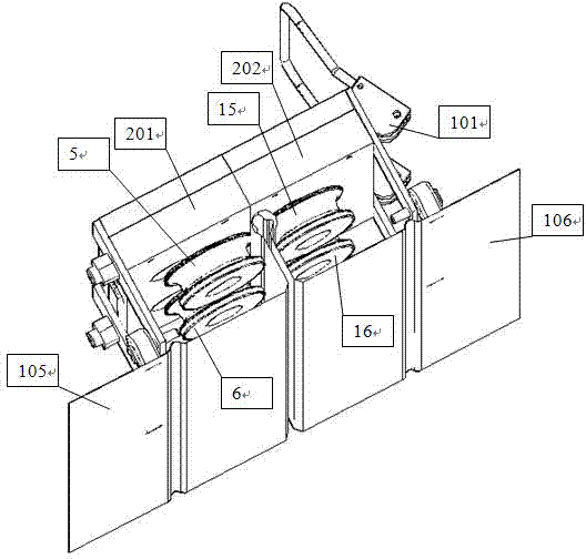
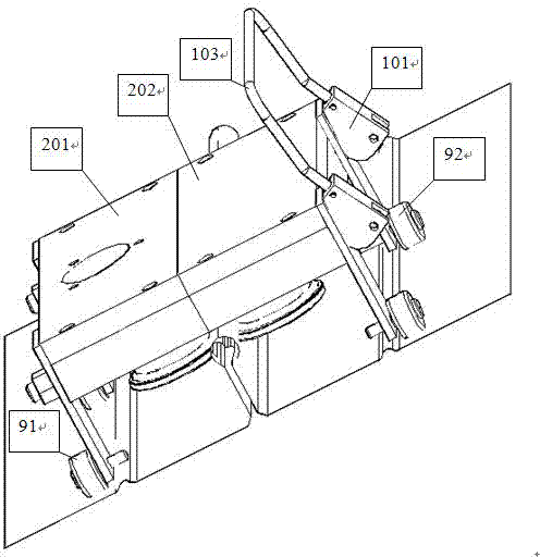
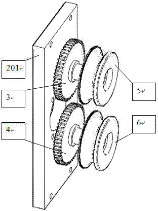
[0016] Such as Figure 1-4 In the shown automatic occlusal device, the frame includes a fixed frame 201 and a movable frame 202, and the fixed frame is provided with rollers 91 for supporting the fixed frame and driving the fixed frame to move. Rollers 92 for supporting the movable frame and driving the movable frame to move are provided. Two guide rods 100 are fixed on the fixed frame, and the axes of the guide rods are parallel to the axes of the rollers. The movable rack slides and is arranged on the guide rod. The cam (locking device) 101 is rotated and arranged at the end of the guide rod. When the cam is rotated, the cam edge can push the movable frame to move along the guide rod to contact the fixed frame, and this state can be locked. A handle 103 is fixed on the locking cam 101 to facilitate the rotation of the cam.

[0017] The mo...


PUM


Abstract

The invention provides an automatic engaging device capable of engaging arc-shaped sides of two sheets. The automatic engaging device comprises a rack, a first driving roller wheel, a first driven roller wheel, a second driving roller wheel and a second driven roller wheel, cambered surfaces at a position where the first driving roller wheel is adjacent with the first driven roller wheel form a first circle with a notch, a roller used for supporting the rack and capable of driving the rack to move is arranged on the rack, a plane passing the axes of the first driving roller wheel and the first driven roller wheel is parallel to the axis of the roller, the axis of the roller is perpendicular to that of the first driving roller wheel, a second circle and the first circle are coaxial, and the diameter of the second circle is smaller than that of the first circle.

Description

technical field [0001] The technology relates to an automatic articulation device. Background technique [0002] In order to snap together the arc-shaped edges (such as color steel) of two plates, tool pliers are generally used to snap them together, which is inefficient and laborious. Contents of the invention [0003] The purpose of this technology is to provide an automatic occlusal device capable of occlusalizing the arc-shaped edges of two plates, which has a simple structure and high processing efficiency. [0004] The automatic occlusal device includes a frame, driven by the power mechanism to rotate the first driving roller arranged on the frame, to rotate the first driven roller arranged on the frame, and the axis of the first driving roller Parallel to the axis of the first driven roller, the first driving roller and the first driven roller are on the same plane, and the opposite surfaces of the first driving roller and the first driven roller are concave arc su...

Claims


Application Information

Patent Timeline
IPC IPC(8): B21D39/02
Inventor 蒋振华
Owner CHANGZHOU ZHENGHUA ELECTROMECHANICAL TECH
Why Eureka
Try Eureka