Crimped/swaged-on tubing terminations and methods

a technology of crimping/swaging-on tubing and terminations, which is applied in the direction of manufacturing tools, mechanical equipment, metal working equipment, etc., can solve the problems of large capital equipment investment, relatively tight tolerances, and significant energy costs, and achieves quick and straightforward, good “bite” and promotes retention

Inactive Publication Date: 2011-06-07
THE GATES CORP
View PDF17 Cites 34 Cited by
  • Summary
  • Abstract
  • Description
  • Claims
  • Application Information

AI Technical Summary

Benefits of technology

[0017]As a further advantage, no heat is employed to practice the present invention. Therefore, typical safety concerns associated with welding and brazing are avoided and weakening of tubing or degradation of tube by annealing, such as may occur during welding or brazing operations, is avoided. Further, the present systems and methods provide a fitting seal without affecting any plating present on the tube.
[0018]Advantageously, embodiments of the present systems and methods provide a quick and straightforward mechanism for providing a fitting-to-tube seal and given the hardness differential between collars used in conjunction with embodiments of the present invention and typical tubing material, good “bite” is provided, promoting retention.
[0021]As a further advantage, the present invention makes use of an annular sealing arrangement instead of mechanical means, such as a weld, solder or braze. Further the present invention provides a separation of functionality between resistance to outside loading and sealing of the interior fluid path.

Problems solved by technology

These are expensive processes that may require significant investment in capital equipment, significant energy costs, relatively tight tolerances for the tubing and fittings, skilled personnel, and post-finishing operations.
Thus, these operations often cannot be utilized at a hose assembly fabricator near the customer and have inherent variability, the quality of which may be difficult to evaluate pre failure.
These factors combine to allow for unacceptable defect level in stems and terminations brazed, soldered or welded onto tubing, resulting in elevated costs and downtime.
Problematically, this deformation of the tube might result in significant deformation of the inner wall of the tube in such a manner as to disrupt or perturb fluid flow through the tube.
Further, such a swaging arrangement is not particularly well suited, for attaching a tubing termination, such as a port or a stem, to a tube.
Such a swaging process may also be time consuming and require costly components, as such it is not necessarily suited to high volume manufacturing.

Method used


Image

  • Crimped/swaged-on tubing terminations and methods
  • Crimped/swaged-on tubing terminations and methods
  • Crimped/swaged-on tubing terminations and methods

Examples


Embodiment Construction

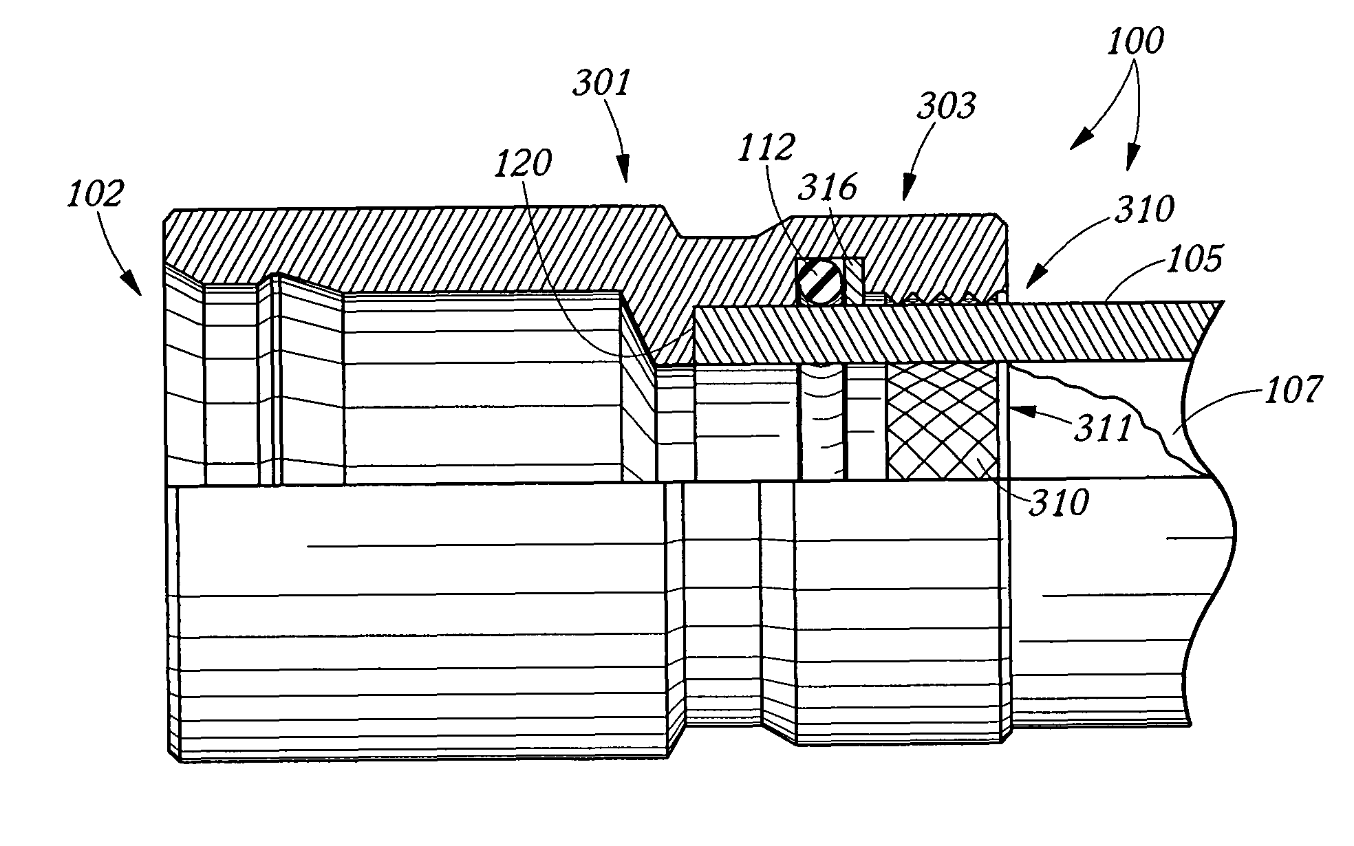
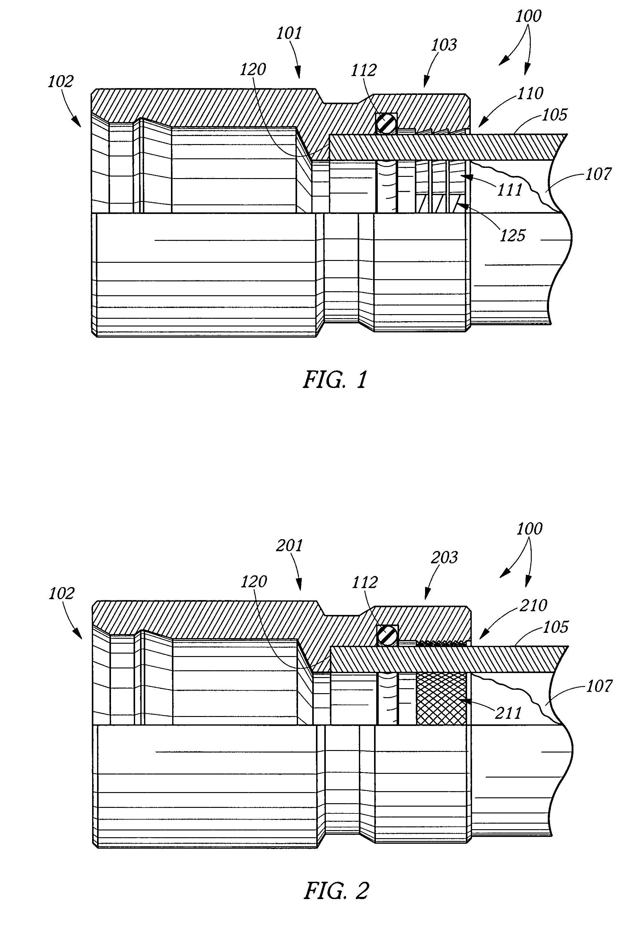
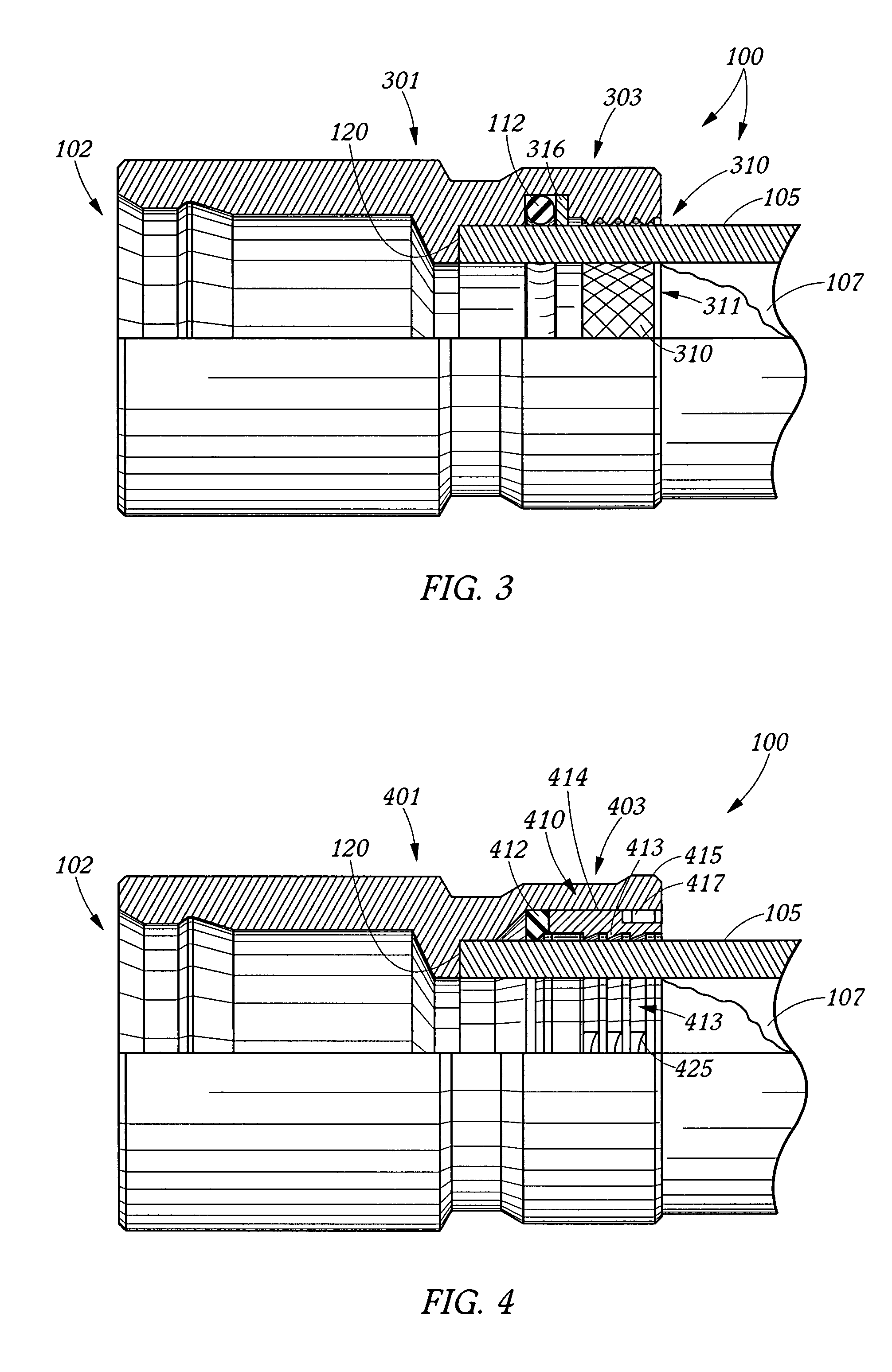
[0032]An embodiment of coupling 100 employing tubing termination 101 of the present invention is shown in FIG. 1. Illustrated tubing termination 101 includes termination portion 102 adapted to make a fluid connection, such as the illustrated port fitting, a stem or a threaded fitting. Illustrated tubing termination 101 also includes tube attachment portion 103, adapted to receive tube 105 and to be crimped or swaged. Tube 105 is shown throughout the drawings in greater fragmentation than tubing termination 101. Preferably, tube attachment portion 103 includes and / or houses retention mechanism 110, shown in FIG. 1 as irregularities, in the form of serrations or teeth, defined by an interior surface 11 of tube attachment portion 103. Preferably, retention mechanism 110 is adapted to be manipulated during crimping or swaging to bite tube 105 so as to lock tube attachment portion 103 relative to tube 105, without significantly deforming inner bore 107 of tube 105. Tube attachment portio...


PUM

PropertyMeasurementUnit
volumeaaaaaaaaaa
pressure forcesaaaaaaaaaa
biting forceaaaaaaaaaa

Abstract

A tubing termination comprises a termination portion adapted to make a fluid connection and a tube attachment portion, adapted to receive a tube and to be crimped or swaged. The tube attachment portion comprises a retention mechanism that is adapted to be manipulated during crimping or swaging to bite the tube so as to lock the tube attachment portion relative to the tube. This retention mechanism may take the form of a deformable bite ring, a deflectable c-insert, irregularities defined on an inner surface of the tube attachment portion, and / or the like. The tube attachment portion also may include a resilient sealing mechanism adapted to provide a seal between the tube and the tube attachment portion, and thereby a fluid-tight connection between the tube and the termination portion.

Description

BACKGROUND OF THE INVENTION[0001]1. Field of the Invention[0002]This invention relates generally to tubing terminations and more particularly to coupling employing crimped-on or swaged-on tubing terminations.[0003]2. Description of the Prior Art[0004]Many hose terminations, such as port fittings or stems, are currently brazed, soldered or welded onto tubing to provide a means for permanently attaching the tubing to hoses or ports. These are expensive processes that may require significant investment in capital equipment, significant energy costs, relatively tight tolerances for the tubing and fittings, skilled personnel, and post-finishing operations. Thus, these operations often cannot be utilized at a hose assembly fabricator near the customer and have inherent variability, the quality of which may be difficult to evaluate pre failure. These factors combine to allow for unacceptable defect level in stems and terminations brazed, soldered or welded onto tubing, resulting in elevate...

Claims


Application Information

Patent Timeline
Patent Type & Authority Patents(United States)
IPC IPC(8): F16L13/14
CPCF16L13/142Y10T29/49908Y10T29/5367Y10T29/49911Y10T29/4994
Inventor SWIFT, JONATHAN C.EYSTER, TODD A.KEAST, GEOFFREY R.GILBREATH, DONALD R.
Owner THE GATES CORP
Why Eureka
Try Eureka