Slab formwork system

a formwork system and slab technology, applied in the field of slab formwork system, can solve problems such as the risk of accidents, and achieve the effect of increasing the economics of the total arrangemen

Active Publication Date: 2013-09-03
PERI GMBH
View PDF14 Cites 6 Cited by
  • Summary
  • Abstract
  • Description
  • Claims
  • Application Information

AI Technical Summary

Benefits of technology

[0010]The limb of the carrier designed as a second hook element can furthermore form a support surface at least sectionally for the support of the

Problems solved by technology

The fact is disadvantageous in the known slab formwork system that formwork elements mounted on the vertical supports can easi

Method used


Image

  • Slab formwork system
  • Slab formwork system
  • Slab formwork system

Examples


Embodiment Construction

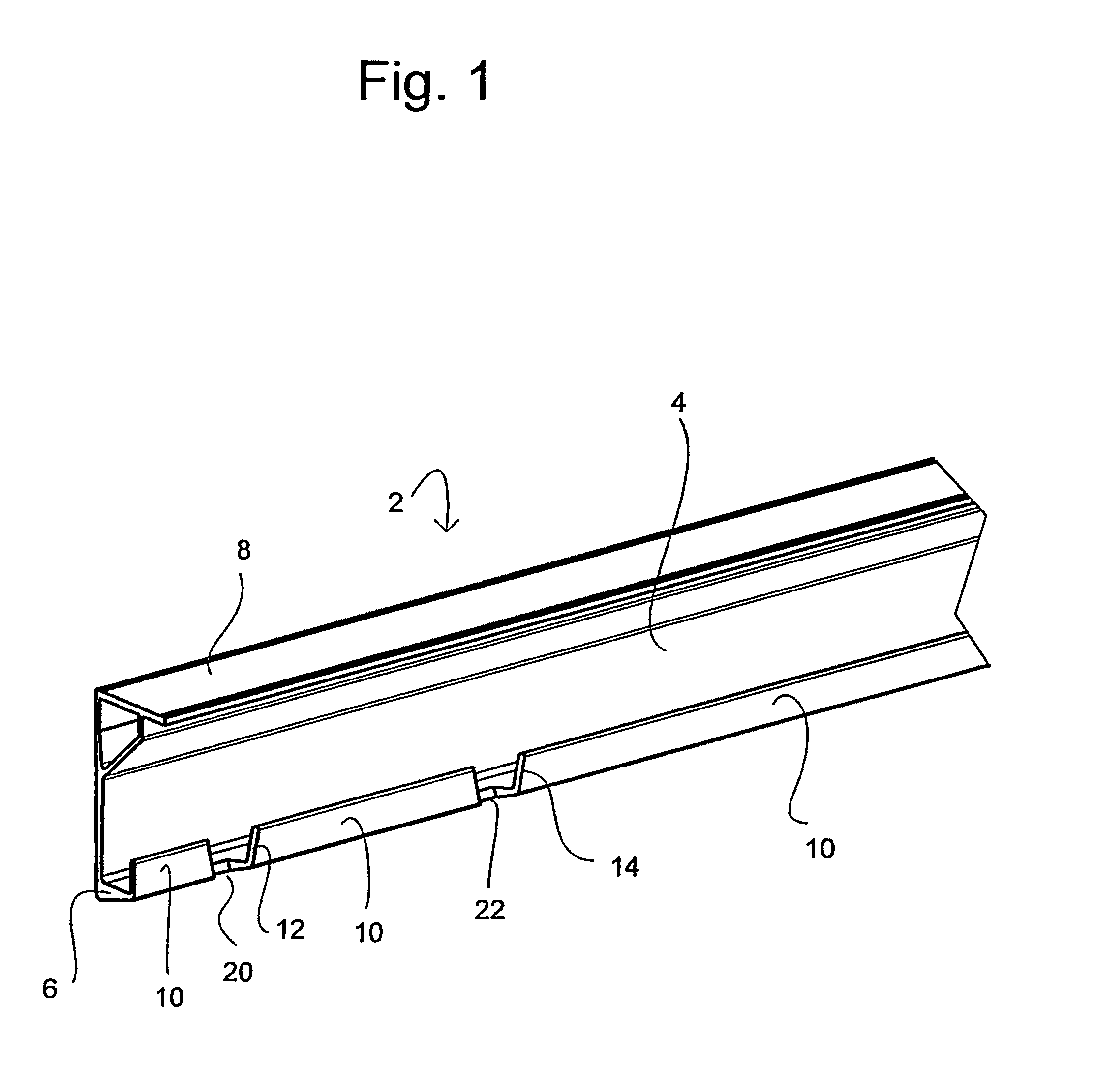
[0048]The carrier 2 shown in FIG. 1 is made as an open elongated section element which has a C-shaped section with two limbs extending away from a base section 4, with the lower limb being designed as a support surface 6 for placing on a head of a vertical support. The upper limb supported at the base section 4 for reinforcement with a diagonal strut 7 forms a support surface 8 for the lower sides of longitudinal members which extend, for example, perpendicular to the carrier 2, which forms a cross member in this case, so that the named longitudinal members, together with the carrier 2 and optionally with further cross members, form a grid element onto which a sheathing can be applied. Alternatively, the contact surface 8 can also serve directly as a contact surface for a sheathing.

[0049]In the carrier 2 shown, the base section 4—viewed in cross-section—is longer than the contact surface 8, which is in turn longer than the support surface 6. The length of the contact surface 8 amoun...


PUM


Abstract

The invention relates to a slab formwork system comprising a plurality of formwork elements (98) which have on their underside girders (2) which can be coupled to heads (28) of vertical supports (90), in which slab formwork system the head of a vertical support has a lifting lock (44-51; 87) fixing a girder of a formwork element in the vertical direction. In addition, the head of a vertical support has fixing elements (52-66) which prevent a movement of the grider in its longitudinal direction.

Description

CROSS-REFERENCE TO RELATED APPLICATIONS[0001]This application is a National Stage of International Application No. PCT / EP2007 / 002825, filed Mar. 29, 2007, and which claims the benefit of German Patent Application No. 10 2006 015 348.0, filed Apr. 3, 2006, the disclosures of both applications being incorporated herein by reference.[0002]The invention relates to a slab formwork system having a plurality of formwork elements which have carriers couplable to heads of vertical supports at their lower side.[0003]A slab formwork system of this type is known from document EP 0 130 425 A1. This system consists of formwork panels at whose lower sides C-shaped carriers are arranged which can be hooked with a head of a vertical support on a substantially vertical alignment of the formwork panels, whereupon the formwork panels can be pivoted into a horizontal position while maintaining the hook connection. To avoid a displacement of the carriers in their longitudinal direction relative to the he...

Claims


Application Information

Patent Timeline
IPC IPC(8): E04G11/00
CPCE04G11/483E04G11/36E04G11/48
Inventor SCHWORER, ARTUR
Owner PERI GMBH
Why Eureka
Try Eureka